Operating principle of the PTO rotational speed indicator:
1. In the absence of the PTO rotational speed sensor, the designations of the
“540” and “1000” scales as well as the indicator of the scale ranges HG11, HG12 light up
simultaneously on starting the engine (when a signal comes from the phase winding of
the alternator).
The indication of the PTO scale segments (with the account of the selected value
of the coefficient “KV2”) occurs on reaching the calculated PTO rotational speed equal to
750 (rpm).
For reference: the indication of the PTO scale segments occurs on reaching the
engine rotational speed of 1400-1500 (rpm) and more.
Here, depending on the selected PTO speed mode (540 or 1000), the lit PTO
scale segments designate the rotational speed values according to Table 10.
Table 10
2. In the presence of the PTO rotational speed sensor installed over the pinion of the
PTO shank, the combined indicator selects automatically the range (320-750 or 750-
1250) depending on the rotational speed of the shank that is accompanied visually by
switching on the backlight of the digital designation of the scale – “540” (HG11) or
«1000» (HG12), here the threshold values of operation of the scale segments change in
accordance with the requirements of Table 10.
The five LED 5 scale segments (HG6 … HG10) of the PTO light up starting from
the bottom one including the segment with the current value of the PTO rotational speed
included in the range of the lit state of that segment.
Notes:
- (*) is the rotational speed value, at which the “1000” scale designation is switched on;
- the “540” scale designation is only switched on in the presence of the signal from the
sensor and switched on switching on the “1000” designation or in case of absence of the
signal for more than 3 s.
- the exact value of the PTO rotational speed can be seen on the indicator РS1.
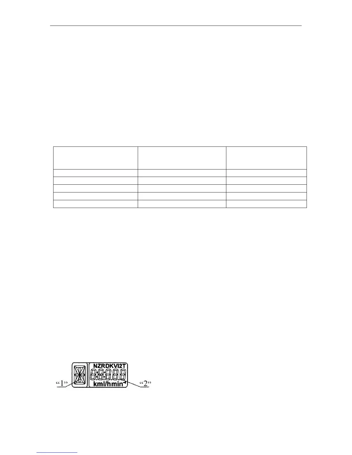
РS1, the LCD multifunction indicator displays simultaneously:
1. Digital designation of the position of the gearbox
control level (digits from 0 to 6) or lettering of the re-
duction gear switch (letters L, M, H, N);
2. Current numerical value of one of the parameters
of the tractor systems.
The combined indicator receives the information on
the position of the gearbox control lever from the
transmission control unit (if the complex electronic control system (CECS) is available) or