Controls and Instrumentation
IMPORTANT! Each time the power supply of the CI is switched ON, the functioning
of the pointer indicators and PTO indicator scale elements is tested. Within one se-
cond after this, the indicator pointers deviate from the initial marks beyond the follow -
ing first marks of the scales (beyond “5” for the motion speed and beyond “10” for the
rotational speed), and all the segments and designations “540” and “1000” of the
PTO scale are switched on.
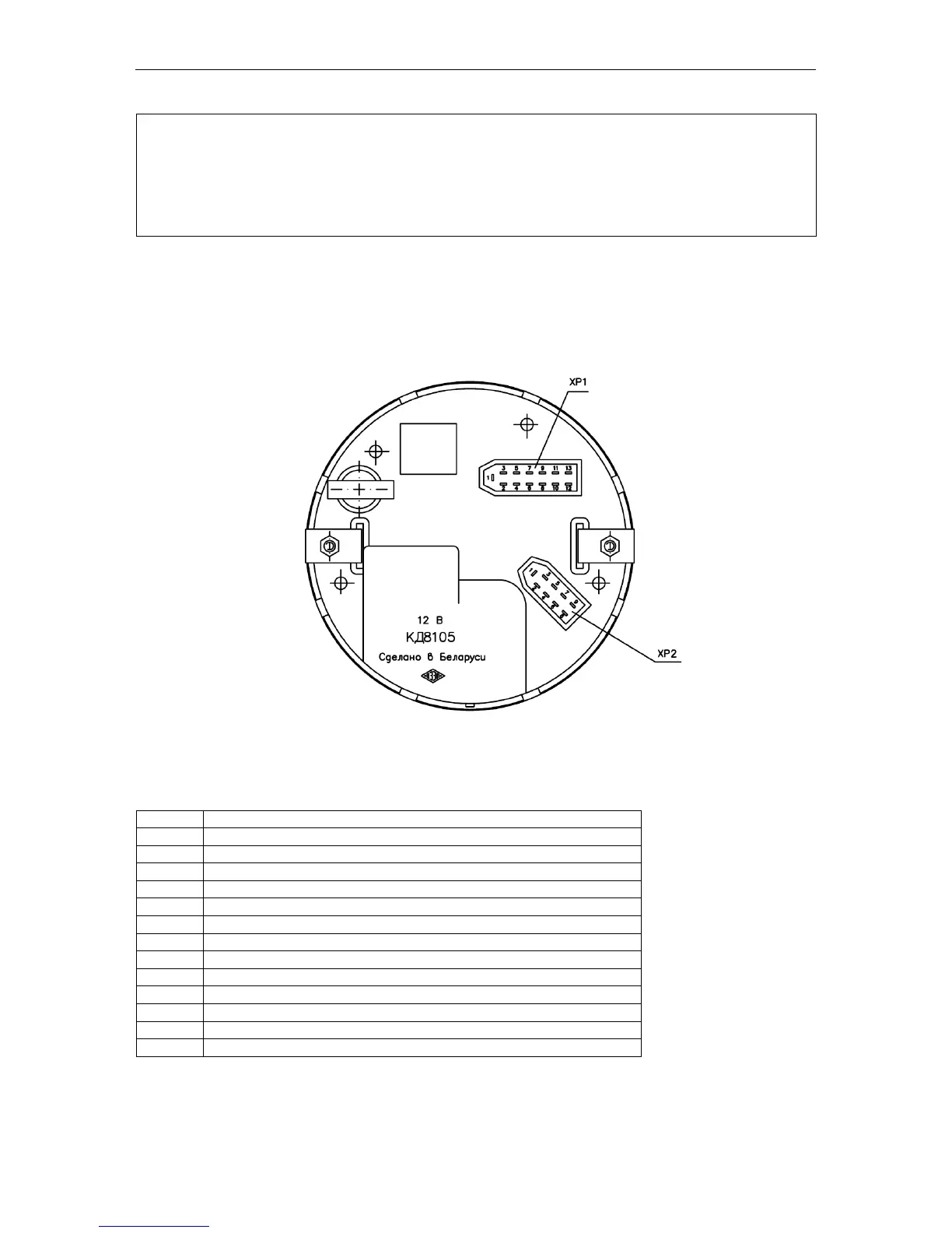
1.11. Connecting the tachospeedometer
To connect the tachospeedometer to the instrumentation system, a 13-contact block
(ХР1) and a 9-contact block (ХР2) are provided on the rear panel of the instrument (Fig.
5).
Fig. 5
The identification of the pins of the blocks is given в Tables (11) and (12).
Table 11
Address of the XP1 connector pin
To the terminal “–“ (common)
To the power supply unit “+12 V”
To the rotational speed sensor “PTO”
To the rotational speed sensor “Left wheel”
To the rotational speed sensor “Right wheel”
To the phase winding of the alternator
To the switch of the backlight
To the switch of the headlight upper beam
To the switch of the trailer turn indicators
To the switch of the parking brake
To the switch of the tractor turn indicators