PIMH0059.docx | Rev 1.1 | Modified on 27/10/2017 | © Remote Control Technologies Pty Ltd
Wiring Connections
Connect to +ve from the igniton switch
3 Yellow/Blue Output1 Park brake +ve to release
Pre-brake aplication alarm - GND 700 mA
6 Orange Input 3 Park brake sense, positive to apply
Door open sense – ground sensing (configurable); the controller will consider the door
closed when the signal is sensed
8 Yellow Input 2 Ground speed frequency input
Time delayed output. This output will come on after the pre-selected time period has
elapsed once the controller has forced the park brake to be applied. This time period
is set to two seconds by default and is configurable.
11 Black/White Not used
12 Red/White Not used
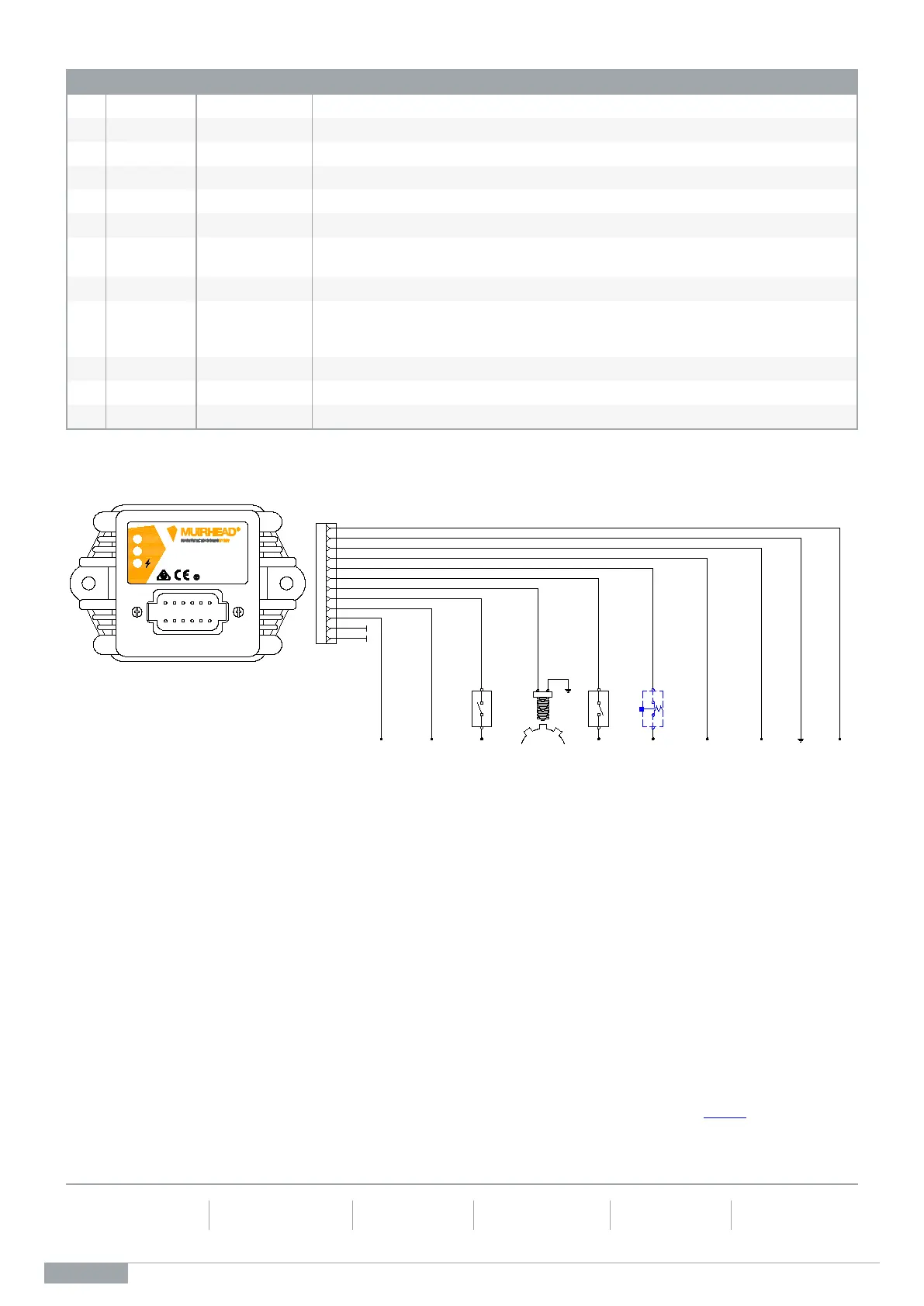
External Wiring Diagram (552e)
For detailed product information, please contact your local RCT branch for a copy of the product manual M0964
. For configuration
settings and adjustment, please contact your local RCT branch to purchase the Muirhead
®
Programming Utility, part number
13647.
Discover more: www.rct-global.com
AUSTRALIA:
AFRICA:
CANADA:
RUSSIA / CIS:
SOUTH AMERICA:
USA:
RD-4
BK/WH-3
WH-FVT
PARK BRAKE
INTERLOCK
12848
PU-FVT
GROUND SPEED
SENSOR
!
www.rct-global.com
GROUNDIGNITION
INPUT
YL/BU-4
OR-4
PRE-APPLICATION
ALARM
(CAN BE CONNECTED
TO LED AND/OR AUDIBLE
ALARM)
PARK BRAKE
INPUT
1
2
3
4
5
6
7
8
9
10
11
12
GN-FVT
PARK BRAKE
POSITIVE TO
APPLY
TIME DELAYED
OUTPUT
BATTERY
SUPPLY
12/24 V
PK-FVT
BK-4
RD/WH-3
YL-FVT
(12848)
DOOR OPEN PARK BRAKE INTERLOCK
CONTROLLER
OPTIONAL
RESET
SWITCH
PARK BRAKE
POSITIVE TO
RELEASE
DOOR
SWITCH
BU-FVT
 Loading...