Z Series Pitch Setting Instructions
Place the locking pin in the groove number that you found in Step 4 above.
If there is an R after the Groove number, align the pin so the elevated offset is to the right of the
groove.
If there is an L after the Groove number, align the pin so the elevated offset is to the left of the
groove.
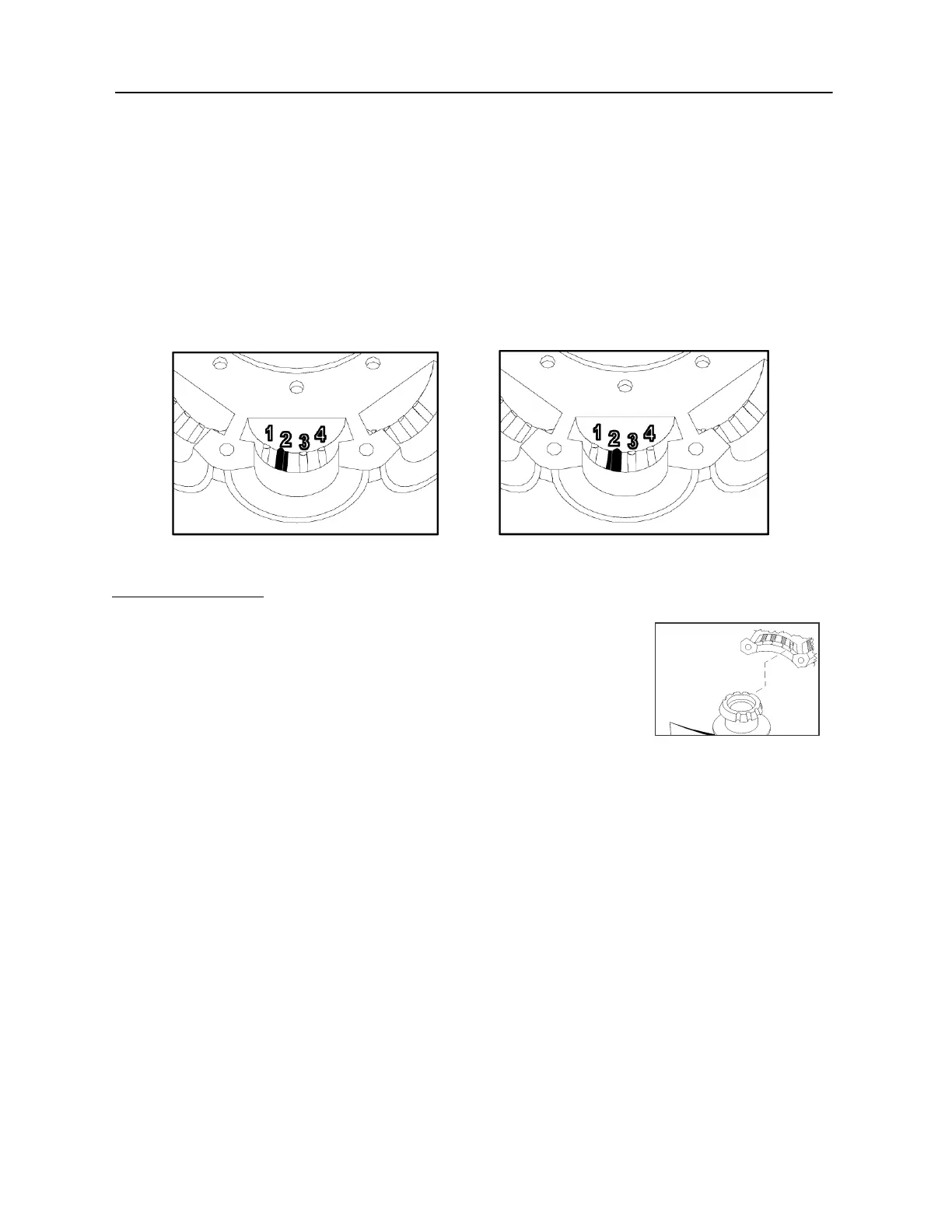
Example:
Pin is set in the 2L Position Pin is set in the 2R Position
To change the offset to the left or right of the groove, the offset pin will need flipped lengthwise.
Finally, Insert Blades:
Place the blade over the pin in the hub/retainer blade socket, so that the
pin also fits into the appropriate pitch angle groove in the blade. See
example picture to the right.
For 6Z fans, use the pitch angle groove in the blade marked with your
rotation (R or L) and pitch angle. Example: L35 is “L” rotation and 35-
degree pitch angle.
Repeat for all blades.
Assemble hubset together, aligning the match marks you made. Replace any balancing weight to its
original position.
To finish, tighten the bolts in a cross pattern to 5 to 6 foot-pounds of torque for the outer bolt circle.
If shaft mounted fan: Mount center hub-boss to retainer plates. Use 5-6 ft lbs of torque for M6 bolts
(qty 5), use 13-15 ft lbs for 5/16-18 bolts (qty 9).
Z pitch setting Rev 4, 11/20/09
 Loading...