CAUTION:
● Note that accuracy will differ, depending upon the diameter of the cable
being measured and in the case of cables with ground wires.
If high-accuracy measurement is required, use the conventional current
transducer.
● In the case of special cables, there are some cables which the universal
current transducer cannot be used to measure.
1) Press the power switch on the right side of instrument.
2) Set the CT selector switch to the “ ⋒ ”position.
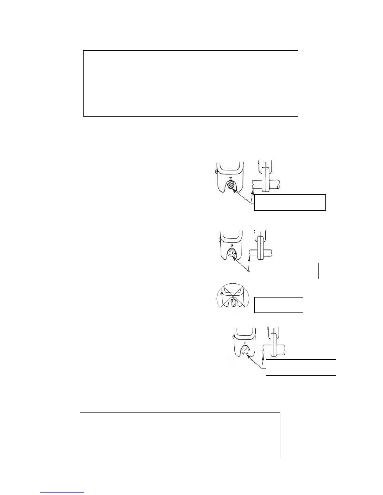
(Measurement of single wire)
① Set the wire selector switch to the “S” position.
② As shown on the right drawing, press the wire
to be measured perpendicularly up against the
▽ mark of the current transducer to measure
the current in the wire.
Note: This instrument is adjusted for IV wires and
will exhibit measurement errors for other type wires.
(Measurement of single-phase wire)
① Set the wire selector switch to the “SP (FLAT)”
position.
② As shown on the right drawing, press the wire
to be measured perpendicularly up against the
▽ mark of the current transducer to measure
the current in the wire.
Note: This instrument is adjusted for VVF wires
and will exhibit measurement errors for other
type wires.
(Measurement of 3-phase wires)
① Set the wire selector switch to the “3P” position
② As shown on the right drawing, press the wire
to be measured perpendicularly up against the
▽ mark of the current transducer.
③ In the condition of ②, rotate the instrument about
the wire to be measured and read the maximum
indication value.
Note: This instrument is adjusted for VVR wires and
will exhibit measurement errors for other type
wires.
 Loading...