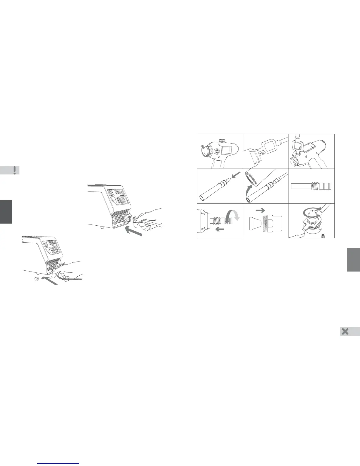
6.6 Torch Assembly
1
2.
(
).
3 Tighten cathode holder retaining screw by turning it clockwise. Do not apply the
significant force when tightening, because the plastic cap of screw may be broken
down. Verify cathode assembly is secure by pulling on it without screw in the outward
direction
4
5.
6
7
8
.
.
. Rotate start button clockwise to hard stop.
. Take cathode assembly and fully insert into torch Rotate cathode assembly around
such that the flat on its tapered end slide into fastener fitting flat is secure if cathode
assembly does not turn Using the combination wrench, insert the cathode assembly
into the torch until the cathode sticks out of the body 19 mm (0.75 inch) for welding
(red mark on wrench) and 17 mm (0.65 inch) for cutting (green mark).
.
. Gently slide quartz tube into thicker end of evaporator.
. Place tapered end of evaporator on a level wooden surface Using thicker end of
plunger, finalize quartz tube installation such that tube end aligns with evaporator
end.
. Install spring into evaporator.
. Rotating evaporator slightly from side to side, slide it over cathode holder keeping it
in alignment.
. Select appropriate nozzle and insert into cap.
9. Place cap and nozzle over protruding section of evaporator making sure there is no
nozzle misalignment Tighten cap clockwise using combination wrench.
It is prohibited:
- to install quartz tube over thinner end of evaporator
6
31
3
4
5 6
7 8
1
2
9
Torch Connection to Power Supply
.
-
-
(see
Figure).
-
.
4.2
- Take cutting torch with
Make certain that power supply ”OFF”
LED is illuminated
Connect torch cable connector to
power supply output connector
Secure connection with connector
latch
green mark
.
4. Cutting - Use distilled water
Study the Safety section and comply with its requirements
Connection of Power Supply
Connect power supply power cable to wall receptacle
- Verify that voltage display and “OFF” LED are illuminated.
Verify that fans are on
.
4.1
-.
-.
Caution
Voltage display may show a value of up to volts if the LED is illuminated
!
5 “OFF” .
18
4
4.3 Power Supply Setup for Torch Start
- Connect MODE II cable with clamp to positive
output on power supply front panel
igure
Press the eft or
(see
F).
-l
5 6 buttons step-by-step
to select position 4 of MODE I current
indicator.
4.4 orch Setup and Servicing
Cutting requires nozzle of diameter . mm, i.e. 0,043-0,051 inches see spare
parts kit To replace nozzle follow Section Steps and Section Steps
Rotate torch start button to set it’s free movement to 2-3 mm (0.08-0.12 inches).
If it is not possible to set free movement to 2-3 mm (0.08-0.12 inches), disassemble
torch (see Section , Steps 5 8-9 and adjust cathode holder position see
Section , Steps 6
see ‘What’s included’
- Open the filling neck cap.
T.
- 1.1-1 3 (
). 6.1, 1 - 3 6.6, 8 -
9.
-
-
6.1 1- , ) (
6.6 1-3, -9).
).
- Take syringe and fill it with water (
 Loading...