Installation
User manual 9000-41011-0200000_hdb_en_20 74 / 92
6.1.3 Mico Pro PD (power distribution)
6.1.4 Mico Pro fix
6.1.5 Mico Pro flex
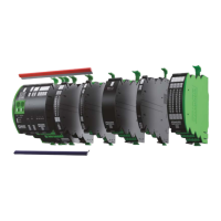
Fig. 6-3: Installation overview
PD 2x12
(Art.-No. 9000-41000-0000212)
1 Not contacted
2 GND/0V bridging contact supply
Plug-In link continuous jumper
3 U+/0V terminal
4 U+/0V terminal
5 U+/0V terminal
6 U+/0V terminal
7 U+/0V terminal
8 U+/0V terminal
9 Internal system connection
10 Unlocking actuator
PD 2x2x06
(Art.-No. 9000-41000-0002206)
1 Not contacted
2 GND/0V bridging contact supply
Plug-In link continuous jumper
3 U1/U2/0V terminal
4 U1/U2/0V terminal
5 U1/U2/0V terminal
6 U1/U2/0V terminal
7 U1/U2/0V terminal
8 U1/U2/0V terminal
9 Internal system connection
10 Unlocking actuator
Fig. 6-4: Installation overview
1 +24V bridging contact supply
Plug-in link continuous jumper
2 GND/0V bridging contact supply
Plug-in link continuous jumper
3 OUT terminal for connecting the consumer circuit
4 GND/0V terminal for connecting the consumer circuit
5 Internal system connection
6 Unlocking actuator
Fig. 6-5: Installation overview
1 +24V bridging contact supply
Plug-in link continuous jumper
2 GND/0V bridging contact supply
Plug-in link continuous jumper
3 OUT terminal for connecting the consumer circuit
4 GND/0V terminal for connecting the consumer circuit
5 Alarm terminals for control output
6 90% terminals for control output
7 ON terminal for control input
8 CTRL terminal for control input
9 Internal system connection
10 Unlocking actuator
 Loading...