Do you have a question about the MyFlyDream Crossbow AAT and is the answer not in the manual?
Vertical Blanking Interval for transmitting flight data via analog video signal.
Using DataRadio with MAVLink protocol for transmitting flight data.
Adjusts yaw offset for precise tracking accuracy.
Manages and selects stored home positions for the tracker.
Calibrates the internal compass for accurate direction sensing.
Calibrates the pitch sub-system to the horizontal position.
Configures how the tracker uses its internal or external compass.
Sets the baud rate for data radio communication.
Displays current flight information like GPS coordinates and altitude.
Configures VBI version for analog video data transmission.
Selects altitude data source (BARO or GPS) for MAVLink tracking.
Accesses factory-level tests and diagnostic functions.
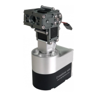
The MyFlyDream Crossbow AAT (Automatic Antenna Tracker) is a precision electromechanical device designed to enhance the signal reception quality for unmanned aerial vehicles (UAVs). Its primary function is to precisely point a ground-based antenna in the current direction of a UAV, thereby ensuring the video receiver picks up the strongest possible signal, especially at greater distances. This is particularly beneficial when using high-gain receiving antennas, which are known for their very narrow effective reception angles.
For successful operation, the Crossbow AAT requires continuous flight data from the UAV, including its latitude, longitude, and altitude. This data can be transmitted to the ground station via several methods. One common method involves transmitting information over a wireless analog video link. For this, the UAV must be equipped with either a MFD Auto Pilot, a MFD Crosshair Auto Pilot, or, if a third-party autopilot is used, an MFD TeleFlyTiny tracking module. The TeleFlyTiny module sends encoded tracking data to the Crossbow AAT via a serial port. Another option is to transmit data over a wireless High Definition video link, again requiring a MFD Auto Pilot, MFD Crosshair Auto Pilot, MAVLink-compatible Auto Pilot, or MFD TeleFlyTiny module on the UAV. Finally, information can be transmitted via a wireless digital data link using the MAVLink protocol, which is supported by many flight controllers and digital radios. If the on-board system already includes a digital radio and a MAVLink-compatible flight controller, the Crossbow AAT can receive all necessary flight information through the shared TXD line of the digital radio station. For custom signal transmission designs, users are advised to contact MFD directly.
The Crossbow AAT is designed for easy installation and power management. It can be fixed to the head of a standard camera/camcorder tripod using a 1/4-20 threaded interface at the bottom of the main unit. Users must ensure their tripod can adequately support the combined weight and leverage of the battery, AAT, and antenna assembly. The device requires a 12V to 16V DC power supply (3S~4S), with a recommended solution being two NP-F980 batteries (7.4V 6600mAh). Powering on the tracker is as simple as plugging an XT60 connector into the corresponding power socket. When mounting antennas, a special bracket must be used. To prevent interference with the internal compass, it is recommended to avoid ferromagnetic materials for antennas and to use non-magnetic stainless steel bolts, aluminum, or other non-magnetic materials where possible. The main unit features an aviation socket for connecting to other equipment like DataRadios or VideoRX, with color-coded wires for clear identification.
For users employing the MAVLink protocol for tracking data via a digital radio link, the digital radio link should be fixed on the antenna bracket. The black wire of the plug cable connects to the ground wire of the digital radio link, and the red wire connects to its power wire. It's crucial to note that the voltage supplied via the red wire (12-16V) might differ from the digital radio's requirements, necessitating a suitable power conversion module if voltages are incompatible. The TX (data output line) of the digital radio link connects to the green line of the cable. Powering on the digital radio link is also necessary. Sharing the TX line with the Crossbow AAT typically does not affect normal ground station operation. The base of the AAT also has two similar aviation sockets, allowing the analog video signal, if fed to the upper socket, to be obtained from the green line of the base socket after passing through an internal slip ring. An RF model of the Crossbow is also available, featuring an internal RF-Slipring, allowing users to mount their antenna on the tracker and access signals up to 3GHz via a lower N-Connector.
To enhance tracking performance, a GPS+Compass module can be chosen. Once plugged in, the Crossbow automatically recognizes it, and the screen displays satellite lock information (e.g., GPS:12/L14 for remote/local GPS satellites). With this module, the tracker initiates tracking once enough satellites are locked, eliminating the need for a manual "set home" operation.
Before operation, the tripod should be securely set up with tightened legs. Upon powering on, the AAT's tilt angle returns to horizontal (0 degrees), and it rotates several times for initialization. The OLED screen displays vital information such as GPS satellite count, battery voltage, distance to the plane, altitude, azimuth, video/data downlink quality, and current tracker heading. Once sufficient satellites are locked (typically 8 or more), pressing the right button on the base sets the home position for the tracker. If using MFD AP/MFD Crosshair, setting the plane's home location also sets the tracker's home. Tracking commences when the plane is at least 10 meters away.
The Crossbow operates in two modes: Unlimited and 450 degrees. In Unlimited mode, the AAT can rotate continuously in one direction. In 450-degree mode, the tracker rotates back 360 degrees upon reaching its limits to prevent cable twisting between the upper rotating part and ground devices. To use this mode, users manually point the tracker to their preferred direction (the opposite direction is rarely used in flight) and then hold the right button for 3 seconds or longer to store this heading as the current favorite direction until power off. This mode allows for a total rotation of 360+45+45=450 degrees.
The Crossbow AAT offers various menu operations for configuration and fine-tuning. To access the menu system, the LEFT button is held for 2 seconds or longer. The LEFT button is used to browse the menu, and the RIGHT button enters sub-menus or changes values. The "YawTrim" and "PitchTrim" settings allow for minor adjustments if the tracker is slightly off in its tracking direction. Negative values trim the tracker to the LEFT, positive values to the RIGHT, and similarly for UP/DOWN pitch adjustments. The valid range for these parameters is [-20,20]. The "HomePos" menu displays recently used home positions (H1-H5, with H1 being the most recent). It shows the distances to these stored positions and their longitude/latitude, helping users select the appropriate home position. A "Load" option allows loading a highlighted home position. The "AutoLoad=N" setting prevents the tracker from loading the most recent home position on startup, which can be enabled by setting it to "Y". This feature is particularly useful if the user forgets to set home before takeoff but has a pre-saved home position. "CalCompass" initiates a compass calibration. Before calibration, the tracker must be securely locked on the tripod. The process takes about 20 seconds, and on-screen parameters can be ignored during this time. "MotorCurr" allows setting the maximum current for the Pitch and Yaw motors (in mA), with a valid range of [0,4500] mA. An "AutoDetect" option helps measure proper settings, but users should ensure the tracker is fastened and clear of objects as it may yaw and pitch in various directions during this procedure. "CalPitch" calibrates the pitch sub-system to ensure the tracker knows its horizontal position. Users adjust the tracker to point to the horizon ("Low Position") and then to approximately 110 degrees ("High Position") using "Pitch UP" and "Pitch DOWN" controls, saving each position before exiting. "CompassMod" defines how the tracker uses its compass. "InitOnly" means the compass is read only at startup to determine North, with an internal optical encoder handling subsequent movements, but tripod rotation is not sensed. "Always" uses the compass continuously, suitable for mounting on vehicles with an external Compass+GPS, though the built-in compass may be inaccurate with high motor loads. "Never" disables compass use, requiring the user to manually point the tracker North (facing the AAT screen South), suitable for fixed installations. "BaudRate" allows selecting the downlink baudrate to match the dataradio setting. "FlightInfo" displays real-time information about the tracked plane, including GPS coordinates (longitude/latitude), Above Sea Level (ASL) altitude from GPS data, and Barometer (BARO) altitude. "PayloadSel" lets users choose the payload level of their setup: "Light" for lightweight antennas, high acceleration, and fast movements; "Midium"; "Heavy"; or "UltraHeavy" for very heavy antennas, low acceleration, and slow movements. "OSDLevel" adjusts the OnScreen Display brightness (Level: 0-100). Higher values result in brighter OSD images, which can overlay graphics information on the analog video signal. With the CAN-BUS and "FlyTogether" feature, up to 10 trackers can be connected, allowing users to see others' relative position/altitude on screen. "VBISetting" configures the VBI level (V1 or V2). V1 is for older MFD products (MFD AP, MFD TeleFlyPro), while V2 is for newer ones (MFD Crosshair AP, MFD TeleFlyTiny). V2 offers better performance over long ranges. This setting determines how analog video carries flying information, which the tracker extracts. "Protocol" allows choosing between "ALT=BARO" or "ALT=GPS" to determine which altitude data from the MAVLink stream is used for tracking. This choice depends on the autopilot's behavior, as MAVLink has multiple altitude data fields. "TrackerID" sets the numeral ID of the tracker (0-9). This ID is displayed on other OSD screens when using the "FlyTogether" function in a CAN-Bus network, requiring a unique ID for each tracker. "SysInfo" displays the firmware version (e.g., Ver.:1.83) and hardware version (e.g., Hw:1). The "Factory" menu, including "Test," "YawTest," "PitchTest," "AllTest," and "CoreData," is reserved for manufacturing purposes.
Troubleshooting tips are provided for common issues, such as the DataRadio not working or VLink displaying 0%. Users are advised to check the "Factory->CoreData->RX" menu to see if the tracker is receiving data from the data radio. If the RX count doesn't increase, cables and DataRadio TX wire should be checked. The "BaudRate" menu should also be verified for correct settings, especially after firmware updates.
Firmware updates for the Crossbow are performed using a dedicated update tool. Users connect the update tool to the tracker, insert the USB plug into a Windows PC, and install the USB-TTL driver if necessary. The MFD FW & update tool (requiring .Net 4.0 framework) is then used. In the update tool, "MFD_AAT" is selected as the device, the correct COM port is chosen, and the firmware file is browsed and selected. After clicking "Update" and confirming, the update process completes in a few seconds. Post-update, users must set the Baudrate, configure motor currents (typically 2000mA for both motors), and calibrate the compass module. If an external GPS+compass module is used, it should be plugged into the tracker before calibration.
| Brand | MyFlyDream |
|---|---|
| Product Name | Crossbow AAT |
| Update Rate | 5Hz |
| GPS Type | Ublox |
| Baud Rate | 9600 |
| GPS Weight | 50g |