Do you have a question about the Myson ECO M 125 and is the answer not in the manual?
Details the intended use of MYSON ECO fans in various premises.
Lists the items included with the MYSON ECO fan.
Specifies the required AC power supply voltage and frequency for operation.
States the maximum ambient air temperature for fan operation.
Confirms compliance with EU norms and directives for electrical equipment.
Details the IP rating for M-series (IP34) and MA-series (IP24).
Emphasizes qualified electrician for connection and cable replacement.
Advises against use by children or persons with limited capabilities without supervision.
Warns against use outside stated temperatures or with aggressive gases.
Prohibits operation that could damage blades and warns against backflow of gases.
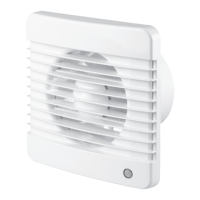
Lists M-series models with their specifications and features like timers and sensors.
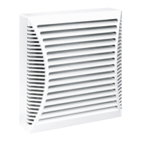
Lists MA-series models with their specifications and features like timers and sensors.
Emphasizes performing all work only after switching off the mains supply.
Details the requirement for using a switch with a minimum 3mm actuation length.
Instructs to align airflow direction and ensure protected access to internal parts.
Guides on removing covers, passing cords, and securing wires to terminals.
Recommends installing a separate switch for fans without a built-in one.
Illustrates wiring for fans with built-in switches (Figs. 7 & 9).
Shows wiring for fans without built-in switches (Figs. 8 & 10).
Explains adjustable delay, humidity activation, and potentiometer settings.
Describes automatic activation by motion and timer-based shutoff.
Warns that timer circuitry is under voltage and requires disconnection for adjustment.
Explains the symbol indicating the product must not be handled as domestic waste.
Instructs to return the product to a designated collection facility at end-of-life.
Highlights how proper disposal prevents negative environmental and health impacts.
Advises contacting local authorities for information on recycling and collection.
| Model | ECO M 125 |
|---|---|
| Category | Fan |
| Brand | Myson |
| Type | Axial Fan |
| Motor Type | AC |
| Finish | White |
| Mounting | Ceiling |