30 of 53
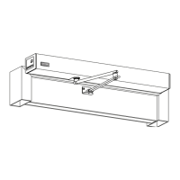
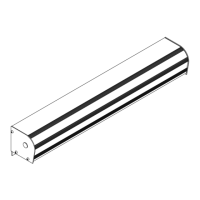
GT1175 (H105 Medium) Hurricane Quick Set-Up and Parts Guide www.NabcoEntrances.com
P/N C-00106 Rev 8-10-16
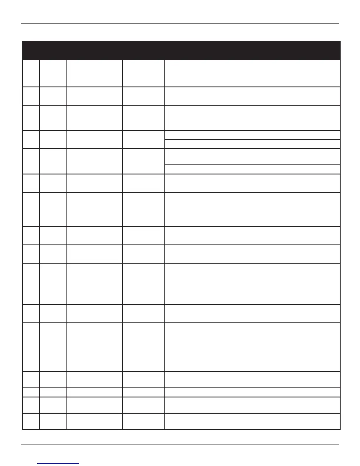
1 9DC 12V 12 VDC+ Brown Output Terminal:
● Sensor power source Output Terminal
● Output is 12 VDC with a maximum capacity of 0.35 amps (350 mA).
2 7 Common Red Output Terminal:
Provides common ground for the 12 VDC power and signal source.
3 61 Interior Acviaon Black Acvaon Signal Input:
Opens the door based on a signal from the Sensor that is acve in one
way mode.
4 6B Holding Beam White Holding Beam Input:
Opens or re-opens a door when the holding beam signal is acvated.
5 H Reduced Opening
Switch
Green Reduced Opening Input:
Enables reduced door opening when switched to Red (7)
6 M0
One Way
Mode Switch Orange Input for Switch 1 (SW1):
Used to achieve special funcons.
7 M1 Night Mode Switch Orange/ White Input for Switch 2 (SW2):
● Used to achieve special funcons.
● All references to Mode Switches are made in connecon with ground
(Red).
8 62 Exterior Acvaon Black/ Red Input Terminal:
Receives signal from a Sensor that is switched out in ONE WAY mode.
9 SQ Sequenal Acvaon Yellow Input Terminal:
Allows a sequence of signals to open and close the door.
10 BA Breakout Detector Blue Input Terminal:
● Connects directly to Red (7) during normal operaon.
● When the Rocker Switch is turned OFF or if the door is panicked
open, it is disconnected from Red (7) causing Slide door to stop
operang.
11 SLS Misellaneous Input Green/ White Input Terminal:
Receives signal from Sidelite Sensor or addional devices.
12 OUT A Auxiliary Output Gray Terminal is connected to the Normally Open contact on an Internal
Relay:
● Also Referred to as the “Auxiliary Relay Output”.
● Used as a switch to sequence Electric Strikes, control other doors in an
Airlock situaon, or signal a Remote Computer on the door operaon.
13 OUT B Auxiliary Output Gray Terminal connected to the Normally Close contact on an Internal
Relay.
14 OUT C Auxiliary Output Violet Terminal is the common for output wire OUT A or OUT B.
15 OUT Auxiliary Output 2 *Brown/ Yellow Terminal connected to an Internal Transistor with open collector in the
U30 Microprocessor Control.
16 7 Common Red Terminal connected to an Internal Transistor with open collector in the
U30 Microprocessor Control.
* Color 1/Color 2 denotes a base wiring Color 1 with a Stripe Color 2 (e.g. Black/Red = Black wire with a Red Stripe)
 Loading...