Do you have a question about the Nalco 3D TRASAR Series and is the answer not in the manual?
Outlines critical safety practices and warnings for installation and operation.
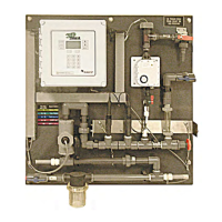
Instructions for unpacking and identifying all system components and hardware models.
Guidelines for selecting and mounting the controller unit, adhering to NEMA4X standards.
Procedures for installing the bio-reporter feed system, either pellet or liquid form.
Details on connecting sample water inlet and outlet plumbing for the controller.
Instructions for plumbing the bio-reporter feeder, ensuring correct water flow and connections.
Guidance on installing various probes such as Fluorometer, pH, ORP, and Corrosion probes.
Comprehensive instructions for electrical connections, including controller box, junction box, and power connections.
Procedures for verifying probe calibration, plumbing, and electrical connections before system startup.
Overview of the final steps to start up the 3D TRASAR system, including configuration and mode activation.
Details how to configure system, control, performance, and relay alarms and thresholds.
Details the options available through the Actions key, including calibration and manual controls.
Describes different types of alarms, including sensor, system, communication, performance, and control alarms.
Explains the Nalco Scale Index (NSI) as a measure of cooling system stress and its correlation to polymer consumption.
Details the start-up procedures for managing scale blowdown control based on system stress.
Outlines the procedures for managing scale control using tagged polymer in 2-drum programs.
Explains the Nalco Bio-Index as a measure of historical system response to biocide feed.
Discusses methods for applying oxidizing biocide, including slug feeds and Bio-Shock mode.
Provides detailed steps for starting up Bio-Control and Bio-Shock modes, including system preparation and configuration.
Describes the automatic operation of the 3D TRASAR Pellet Feeder for dispensing bio-reporter pellets.
Details how to use the 3D TRASAR Web for monitoring system performance, alarms, and reports.
Provides a monthly maintenance schedule for system components to ensure reliability.
Step-by-step instructions for cleaning the fluorometer flow cell to prevent fouling and ensure accurate readings.
Details the recommended calibration procedures and frequency for various sensors.
A table listing common problems, their possible causes, and solutions for system issues.
Provides guidance on troubleshooting common alarm conditions displayed on the controller screen.
| Brand | Nalco |
|---|---|
| Model | 3D TRASAR Series |
| Category | Water System |
| Language | English |