EasyManua.ls Logo

NAPCO FIREWOLF FW-2-E - User Manual

NAPCO FIREWOLF FW-2-E
2 pages
Print Icon
To Next Page IconTo Next Page
Loading...
333 Bayview Avenue, Amityville, New York 11701
For Sales and Repairs, (800) 645-9445
For Technical Service, (800) 645-9440 or visit us at Tech.NapcoSecurity.com
(Note: Technical Service is for security professionals only)
Publicly traded on NASDAQ Symbol: NSSC
WI2485ALF 01/23
PAGE 1 of 2
INSTALLATION AND MAINTENANCE INSTRUCTIONS
Connect these detectors only to a Napco listed-compatible control panel: Series GEM-P816, GEM-P1632, GEM-
P1664, F-64, Series GEM-P3200, GEM-P9600, GEM-X255, Series GEMC-32, GEMC-96, GEMC-128, GEMC-255, Series
FL-32FACP-xxxxx, FL-96FACP-xxxxx FL-128FACP-xxxxx, FL-255FACP-xxxxx, Series XP-600, GEM-P800, GEM-P801.
Refer to the control panel installation manual for additional instructions. Smoke detectors are not to be used with
detector guards unless the combination has been evaluated and found suitable for that purpose.
FW-2-E Conventional Photoelectric Smoke Detector and Base
Sensing Element Smoke IR LED, Blue LED, Photodiode
Blue LED enhances the photoelectric smoke sensor to reduce sensitivity
to false alarms and increase sensitivity to fire conditions.
Supply Voltage Operating Voltage Range 8 35VDC
Maximum Voltage Ripple 8200mVAC
Current Consumption Standby Current
59A
Alarm Current 5mA (Min), 150mA (Max)
Startup Cold Start Time 25s (Max)
Alarm Verification Restart
Time
20s (Max)
Current
160A (Max)
Included Separable Base FW-2-EH6-BASE (HB-55) 6 inch diameter base
Included Separable Head FW-2-E-HEAD (Detector ID HD-3) Smoke Detector
Temperature UL Listed Ambient: 32F ~ 120F, Storage: -22F ~ +140F
Operating Humidity <95%RH at 104F, <80%RH at 120F
FW-2-H-E Conventional Photoelectric Smoke and Heat Detector and Base
Sensing Element Smoke IR LED, Blue LED, Photodiode
Blue LED, thermistor enhance the photoelectric smoke sensor to reduce
sensitivity to false alarms and increase sensitivity to fire conditions.
Heat Thermistor
Heat Sensitivity Range 135F
Supply Voltage Operating Voltage Range 8 35VDC
Maximum Voltage Ripple 8200mVAC
Current Consumption Standby Current
59A
Alarm Current 5mA (Min), 150mA (Max)
Startup Cold Start Time 25s (Max)
Alarm Verification Restart
Time
20s (Max)
Current
160A (Max)
Included Separable Base FW-2-EH6-BASE (HB-55) 6 inch diameter base
Included Separable Head FW-2-H-HEAD (Detector ID HD-3) Smoke and Heat Detector
Temperature UL Listed Ambient: 32F ~ 117F, Storage: -22F ~ +140F
Operating Humidity <95%RH at 104F, <80%RH at 120F
SEPARABLE BASE SPECIFICATIONS
MODEL Base ID Alarm Current Mounting Box
FW-2-EH6-BASE HB-55 150mA
limit by panel
@15.0 - 33.0V max 4”Octogonal / 4”Square
CAUTION
Install this and all life safety devices in accordance with applicable NFPA standards, local codes, and the authorities
having jurisdiction. Failure to follow these instructions may result in failure of the detector to initiate an alarm condition.
Napco Security Systems, Inc. and the original equipment manufacturer, are not responsible for detectors that have been
improperly installed, tested, or maintained.
Question and Answer IconNeed help?

Do you have a question about the NAPCO FIREWOLF FW-2-E and is the answer not in the manual?

Overview

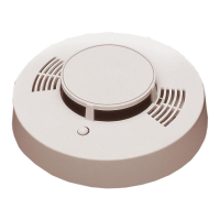
The device described in this manual is a FW-2-E Conventional Photoelectric Smoke Detector and Base and a FW-2-E-H Conventional Photoelectric Smoke and Heat Detector and Base. These devices are designed to detect smoke and, in the case of the FW-2-E-H, heat, as part of a fire alarm system. They are intended for use in commercial and industrial settings.

Function Description:

Both models utilize an infrared (IR) LED and a blue LED, along with a photodiode, to detect smoke. The photoelectric smoke sensor is designed to reduce sensitivity to false alarms and increase sensitivity to fire conditions. This is achieved by using a smooth ceiling mount and, in some cases, by reducing spacing at the perpendicular of the obstructions. The FW-2-E-H model adds a thermistor for heat detection, providing an additional layer of protection.

The detectors are designed to be connected to a control panel. When smoke or heat is detected, the device signals the control panel, initiating an alarm condition. The manual emphasizes that these devices are part of a life safety system and must be installed, maintained, and operated in accordance with all applicable national, state, and local codes and authorities having jurisdiction.

Important Technical Specifications:

FW-2-E Conventional Photoelectric Smoke Detector and Base:

  • Operating Voltage Range: 8 – 35VDC
  • Maximum Voltage Ripple: 8200mVAC
  • Standby Current: 50µA
  • Alarm Current: 5mA (Min), 150mA (Max)
  • Cold Start Time: 25s (Max)
  • Alarm Verification Restart Time: 20s (Max)
  • Current (Alarm): 160µA (Max)
  • Included Separable Base: FW-2-EHE-BASE (HB-55) 6 inch diameter base
  • Included Separable Head: FW-2-E-HEAD (Detector ID HD-3) Smoke Detector
  • Temperature Operating Humidity: UL Listed Ambient: 32°F – 120°F, Storage: -22°F – +140°F; <95%RH at 104°F, <80%RH at 120°F

FW-2-E-H Conventional Photoelectric Smoke and Heat Detector and Base:

  • Operating Voltage Range: 8 – 35VDC
  • Maximum Voltage Ripple: 8200mVAC
  • Standby Current: 50µA
  • Alarm Current: 5mA (Min), 150mA (Max)
  • Cold Start Time: 25s (Max)
  • Alarm Verification Restart Time: 20s (Max)
  • Current (Alarm): 160µA (Max)
  • Included Separable Base: FW-2-EHE-BASE (HB-55) 6 inch diameter base
  • Included Separable Head: FW-2-E-HEAD (Detector ID HD-3) Smoke and Heat Detector
  • Temperature Operating Humidity: UL Listed Ambient: 32°F – 117°F, Storage: -22°F – +140°F; <95%RH at 104°F, <80%RH at 120°F

Separable Base Specifications (Common to both models):

  • Model: FW-2-EHE-BASE
  • Base ID: HB-J5
  • Alarm Current: 150mA (max) @15.0 - 33.0V max
  • Mounting Box: 4" Octagonal / 4" Square

Usage Features:

  • Wiring Detectors: The manual provides a diagram for wiring the detectors to a 3M Weatherban #606 nonflammable sealing compound (or equivalent) to reduce the stack effect. The detector base includes terminals for connection to the control panel.
  • Placement of Detectors: Detailed guidelines are provided for detector placement, emphasizing compliance with local codes and the authority having jurisdiction. Factors to consider include:
    • Contents of space
    • Involved height of ceiling
    • Surface condition of ceiling
    • Total area
    • Air movement (stratification)
    • Vent location (velocities and dilution)
    • Deflections and obstructions
  • Spacing: One smoke detector covers approximately 450 to 900 square feet. For smooth ceilings, detectors can be placed on 30-foot centers. For ceilings with beams or other obstructions exceeding 8" but less than 18", reduced spacing at the perpendicular of the obstructions is recommended. For obstructions exceeding 18", additional detectors may be required.
  • Testing: The manual outlines a testing procedure for the FW-2-E/FW-2-E-H detectors. This involves:
    1. Holding a magnet (2lb pull force min) on the detector as shown.
    2. The detector will blink red.
    3. The detector will cause the alarm to illuminate a continuous red LED.
    4. For no-go: The detector will continue to blink red and never alarm or latch red.
    5. Upon reset, the detector LED should flash Green.
  • Caution on Aerosol Smoke Contaminants: The manual warns against using aerosol smoke contaminants for testing, as they can damage the detector. Instead, it recommends using Sabre aerosol cans or Testifier 1000/1001 or 2000/2001 with TS3 smoke capsules/heat setting per manufacturer's instructions.

Maintenance Features:

  • Cleaning: The manual advises that dry compressed air can be used to remove dust from a detector. If the detector fails to initiate an alarm condition or initiation of a false alarm condition, it should be removed from service.
  • Testing: Regular testing is crucial for effective operation. The manual specifies that combustion products must enter the outer chamber for the detector to operate efficiently. Airflow, stratification, velocity, stagnation, and migration all affect the efficiency and accuracy of the detector. Users should use an air flow meter to determine the movement of air within a structure. Compliance with local codes and ordinances for maintenance requirements is emphasized, including annual functional testing and visual inspection.
  • Troubleshooting: Prior to testing any detector, care should be exercised to ensure proper disabling of live signals and notification circuits of the fire alarm control panel. Failure to do so may result in false alarm signals which could place life and property in jeopardy.

The manual also includes a "CAUTION" section emphasizing that all life safety devices, including fire alarm equipment, must be installed, operated, and maintained according to manufacturer's instructions and all applicable codes. Failure to follow these instructions may result in failure of the detector to initiate an alarm condition. Napco Security Systems, Inc. disclaims responsibility for any devices that have been improperly installed, used, or maintained.

NAPCO FIREWOLF FW-2-E Specifications

General IconGeneral
BrandNAPCO
ModelFIREWOLF FW-2-E
CategorySmoke Alarm
LanguageEnglish

Related product manuals