AA38-3xx Series Local ICS Loop
SM37 Installation and Operation Manual
Section 2 Rev: 1.00 Issue 4 Page 2-3
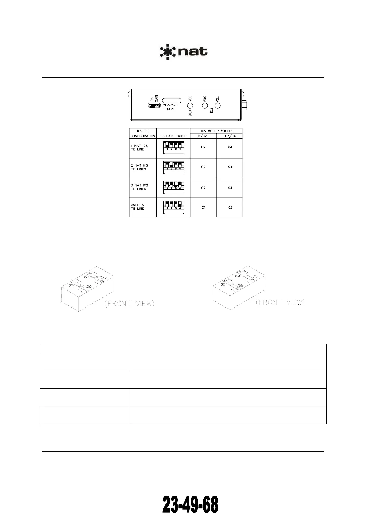
Figure 1: Switch Configurations
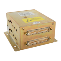
The rocker switches used to configure the AA38 for the appropriate tie line option are visible through the
ICS MODE opening(s) in the side of the unit. The diagrams below show one set of rocker switches for the
AA38-300 and two for the AA38-301.
OR
Figure 2: ICS MODE Switch positions for
1, 2, or 3 NAT ICS Tie Lines
Figure 3: ICS MODE Switch Positions
for ANDREA Tie Lines
Mode Switch Positions
1 NAT ICS Tie Line ICS GAIN switch #1 DOWN, ICS GAIN switches # 2, 3, and 4 UP
ICS MODE switch: C1/C2 to C2 and C3/C4 to C4 (See figure 2)
2 NAT ICS Tie Lines ICS GAIN switch #2 DOWN, ICS GAIN switches # 1, 3, and 4 UP
ICS MODE switch: C1/C2 to C2 and C3/C4 to C4 (See figure 2)
3 NAT ICS Tie Lines ICS GAIN switch #3 DOWN, ICS GAIN switches # 1, 2, and 4 UP
ICS MODE switch: C1/C2 to C2 and C3/C4 to C4 (See figure 2)
ANDREA Tie Lines ICS GAIN switch #4 DOWN, ICS GAIN switches # 1, 2, and 3 UP
ICS MODE switch: C1/C2 to C1 and C3/C4 to C3 (See figure 3)
Table 1
Mode and Switch Positions
ENG-FORM: 805-0117.DOT
CONFIDENTIAL AND PROPRIETARY TO NORTHERN AIRBORNE TECHNOLOGY LTD.
The document reference is online, please check the correspondence between the online documentation and the printed version.