EasyManua.ls Logo

Natco Fire Coil 85 User Manual

Default Icon
40 pages
To Next Page IconTo Next Page
Page #1 background imageLoading...
Page #1 background image
Installation and Operation Instructions Document 1241
H2XXXXXXX-
Hydronic Boiler
Model F85H
Volume Water Heater
Model F85V
Sizes 500–2000 MBTU/h
WARNING
If the information in this manual is not
followed exactly, a fire or explosion may
result causing property damage, personal
injury or loss of life.
Do not store or use gasoline or other
flammable vapors and liquids in the vicinity
of this or any other appliance.
WHAT TO DO IF YOU SMELL GAS
Do not try to light any appliance.
Do not touch any electrical switch; do not
use any phone in your building.
Immediately call your gas supplier from a
nearby phone. Follow the gas supplier's
instructions.
If you cannot reach your gas supplier, call
the fire department.
Installation and service must be performed by
a qualified installer, service agency, or gas
supplier.
AVERTISSEMENT
Assurez-vous de bien suivres les instructions
données dans cette notice pour réduire au
minimum le risque d’incendie ou d’explosion ou
pour éviter tout dommage matériel, toute
blessure ou la mort.
Ne pas entreposer ni utiliser d’essence ni
d’autres vapeurs ou liquides inflammables dans
le voisinage de cet appareil ou de tout autre
appareil.
QUE FAIRE SI VOUS SENTEZ UNE ODEUR DE GAZ:
Ne pas tenter d’allumer d’appareils.
Ne touchez à aucun interrupteur. Ne pas vous
servir des téléphones dansle bâtiment où
vous vous trouvez.
Appelez immédiatement votre fournisseur de
gaz depuis un voisin. Suivez les instructions
du fournisseur.
Si vous ne pouvez rejoindre le fournisseur de
gaz, appelez le sservice des incendies.
L’installation et l’entretien doivent être assurés par
un installateur ou un service d’entretien qualifié ou
par le fournisseur de gaz.
FOR YOUR SAFETY: This product must be installed and serviced by a professional service technician,
qualified in hot water boiler installation and maintenance. Improper installation and/or operation could
create carbon monoxide gas in flue gases which could cause serious injury, property damage, or death.
Improper installation and/or operation will void the warranty. For indoor installations, as an additional
measure of safety, NATCO strongly recommends installation of suitable Carbon Monoxide detectors in the
vicinity of this appliance and in any adjacent occupied spaces.
Installation and Operation Instructions for
Fire Coil 85

Table of Contents

Question and Answer IconNeed help?

Do you have a question about the Natco Fire Coil 85 and is the answer not in the manual?

Natco Fire Coil 85 Specifications

General IconGeneral
BrandNatco
ModelFire Coil 85
CategoryBoiler
LanguageEnglish

Summary

SECTION 1. General Information

1.1 Introduction

Provides necessary information for installation, operation, and maintenance.

1.2 Model Identification

Describes the model number structure and its components for identification.

1.3 Warranty

Details the limited warranty coverage, registration, and claim process.

1.4 Dimensions

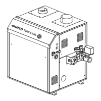
Refers to figures for dimensional data of the appliance.

1.5 Locating the Appliance

Guidelines for selecting a proper installation location, clearances, and site requirements.

1.6 Locating Pump-Mounted Water Heater with Respect to Storage Tank(s)

Specifies optimal placement for pump-mounted water heaters relative to storage tanks.

1.7 Locating Pump-Mounted Boiler with Respect to Return/Supply Header

Guidelines for locating pump-mounted boilers concerning supply and return headers.

1.8 Locating Appliance for Correct Horizontal Vent/Ducted Air Distance from Outside Wall

Requirements for positioning vent and combustion air terminals relative to outside walls.

SECTION 2. Venting and Combustion Air

2.1 Combustion Air

Details requirements for providing combustion and ventilation air to the appliance.

2.1.1 Combustion Air From Room

Explains methods for supplying combustion air from the installation space.

2.1.2 Intake Combustion Air

Describes how to take combustion air through the wall or roof using specific terminals.

2.2 Venting

Discusses vent categories, requirements, and system types for appliance venting.

2.2.1 Vent Categories

Explains how the appliance can be classified as Category I or Category III venting.

2.2.2 Category I Vent

Outlines standards and requirements for Category I venting systems.

2.2.3 Common Venting Systems

Addresses safety concerns and requirements for common venting with other appliances.

2.2.4 Category III Vent

Details requirements for Category III venting systems, typically horizontal discharge.

2.3 Locating Vent & Combustion Air Terminals

Provides guidelines for the proper placement of vent and air intake terminals.

2.3.1 Side Wall Vent Terminal

Specifies requirements for installing side wall vent terminal locations and clearances.

2.3.2 Side Wall Combustion Air Terminal

Details requirements for installing side wall combustion air terminal locations and clearances.

2.3.3 Vertical Vent Terminal

Outlines requirements for vertical vent terminal height and placement above the roof.

2.3.4 Vertical Combustion Air Terminal

Explains requirements for vertical combustion air terminals when taken from the roof.

2.4 Common Vent Test - Boilers

Describes procedures for testing common venting systems after appliance removal.

SECTION 3. Gas Supply and Piping

3.1 Gas Supply and Piping

Details pipe sizing, support, valve installation, and leak testing for gas supply.

SECTION 4A. Water Connections — Boiler

4A.1 Heating System Piping: Hot Supply Connections — Boiler

Details hot supply piping connections, pressure requirements, and support for the boiler.

4A.2 Cold Water Make-Up — Boiler

Explains how to connect the cold water supply to the boiler's automatic fill valve.

4A.3 Water Flow Requirements — Boiler

Specifies water flow rates needed for boilers to ensure proper operation and longevity.

4A.4 Freeze Protection - Boiler

Advises on precautions for installations in areas prone to freezing conditions.

SECTION 4B. Water Connections — Water Heaters

4B.1 Water System Piping — Water Heater

Details piping, support, and pump considerations for water heater installations.

4B.2 Hot Water Supply Piping — Water Heater

Outlines guidelines for connecting the hot water supply piping to the water heater.

4B.3 Water Flow Requirements — Water Heater

Specifies water flow rates for water heaters to prevent scaling and erosion.

4B.4 Combined Water Heating (potable) and Space Heating - Water Heater

Discusses considerations for systems providing both potable hot water and space heating.

4B.5 Freeze Protection – Water Heater

Advises on precautions for water heater installations in areas subject to freezing.

SECTION 5. Electrical Connections

5.1 Main Power

Details the requirements for connecting the main 120-volt fused power supply.

5.2 Field Wiring

Explains how to connect field wiring for main power and pump power.

5.3 External Staging Control Wiring

Provides instructions for wiring external controls to manage unit staging.

SECTION 6. Operating Instructions

6.1 Sequence of Operation

Describes the step-by-step process the appliance follows during a heating cycle.

6.3 Operating Temperature Control

Explains how to set and use the appliance's temperature control and aquastat.

6.4 External Boiler Operations

Details how to operate the unit when controlled by an external source.

6.5 Limit Controls

Discusses the function and importance of manual reset and automatic high limit controls.

6.6 Operating the Burner and Set Up

Instructions for initial burner setup and operation checks.

6.6.1 Set Up for 0 to 2500 Feet Altitude

Specific procedures for setting up the appliance at lower altitudes.

6.6.2 High Altitude Adjustment and Set Up

Guidelines for adjusting the appliance for optimal performance at high altitudes.

6.7 Shutting Down the Fire Coil 85

Procedures for safely shutting down the appliance.

6.8 To Restart the Fire Coil 85

Steps for restarting the appliance after it has been shut down or drained.

SECTION 7. Maintenance

7.1 System Maintenance

Covers regular checks and cleaning of system components like pumps and strainers.

7.2 Appliance Maintenance and Component Description

Details maintenance procedures for specific appliance components.

7.2.1 Burners

Instructions for inspecting and cleaning the appliance's burners.

7.2.2 Filter

Guidance on inspecting, cleaning, and replacing the air filter.

7.2.3 Gas Valves

Procedures for removing, installing, and checking gas valves.

7.2.4 Manual Reset High Limit Control

Steps for replacing the manual reset high limit switch.

7.2.5 Temperature Control

Instructions for replacing the temperature control unit.

7.2.6 Ignition Controls

Procedures for replacing the ignition controls.

7.2.7 Ignitors/Sensor

Steps for replacing the hot surface ignitor/sensor assembly.

7.2.8 Transformer

Guidance on replacing the appliance's transformer.

7.2.9 Blowers

Instructions for replacing the combustion air blowers.

7.2.10 Flow Switch

Information on the paddle-type flow switch and its function.

7.2.11 Heat Exchanger Coil

Important safety warning and steps for cleaning the heat exchanger.

SECTION 8. Trouble Shooting

8.1 Resolving Lockouts

Identifies common causes of appliance lockouts and how to resolve them.

8.2 Delayed Ignition — Possible Causes

Discusses potential causes for delayed ignition and troubleshooting steps.

8.3 Short Cycling — Boiler

Explains potential causes of short cycling in boiler applications.

8.4 Short Cycling - Water Heater

Discusses potential causes of short cycling in water heater applications.

8.5 High Gas Consumption

Addresses causes of high gas consumption and how to adjust for efficiency.

SECTION 9. Replacement Parts

9.1 General Information

Guide on how to order replacement parts through dealers or customer service.

9.2 Parts List

Refers to the subsequent pages for a comprehensive list of replacement parts.

Related product manuals