EasyManua.ls Logo

National Comfort Products CPE42310-U User Manual

Default Icon
28 pages
To Next Page IconTo Next Page
Page #1 background imageLoading...
Page #1 background image
Installation Manual for Comfort Pack Electric Units
Installation
Manual
Comfort Pack Electric
Universal Series
12 SEER
ELECTRIC HEAT
This unit should be installed in an
OUTSIDE WALL for THRU-THE-WALL
INSTALLATION ONLY!
Read Installation Manual prior to starting the installation.
This manual must be left with the homeowner for future reference.
National Comfort Products
A Division of National Refrigeration and Air Conditioning Products, Inc.
539 Dunksferry Road • Bensalem, PA 19020-5908
(800) 523-7138 • Fax (215) 639-1674
www.nationalcomfortproducts.com
Go Thru-the-Wa
CPE
U-Models
Optional
Electric
Heating
Electric
Cooling
HEATING & A/C EQUIPMENT
NATIONAL
COMFORT
PRODUCTS
®
C
C
MF
MF
RT PACK
RT PACK
Thru-the-Wa Comfort for a types of Multi-Family Construction
Question and Answer IconNeed help?

Do you have a question about the National Comfort Products CPE42310-U and is the answer not in the manual?

National Comfort Products CPE42310-U Specifications

General IconGeneral
BrandNational Comfort Products
ModelCPE42310-U
CategoryHeating System
LanguageEnglish

Summary

Comfort Pack Nomenclature

Safety First!

Unit Operation

Before You Start

Installation Compliance Caution

Chassis Removal Procedure

General Installation Guidelines

Drainage System

Secondary Drain Trap Installation

Instructions for installing and priming the secondary drain trap.

Installation Clearances

Unit Location Considerations

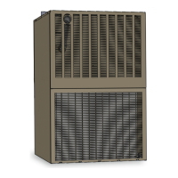
General requirements and cautions for unit placement and wall opening.

Electrical Requirements

Electrical Supply and Connections

Guidelines for power supply, wiring, and disconnect switches.

Low Voltage Electrical

Maximum wire lengths for low voltage thermostat wiring.

High Voltage Electrical

Wiring Schematic for Electric Heat

Wiring diagram for electric heat models with different kW ratings.

High Voltage Diagrams

Maintenance and Service

Cooling Chassis Servicing

Information on removing and servicing the cooling chassis.

Dimensional Drawings

Performance Data

Electrical Data Summary

Electrical specifications including RLA, LRA, HP, FLA, and circuit amps.

Airflow Data @208 Volts

Airflow Data @230 Volts

Electric Air Flow Data

0Kw Wiring Schematic

Wiring Schematic for 3, 5, 7, 10Kw Electric Heat

Wiring Schematic for 15Kw Electric Heat

Replacement Parts Guide (Cabinet & Furnace)

Replacement Parts Guide (Chassis)

Warranty Compressor Removal Procedure

Limited Warranty Information

Warranty Claim Procedure

Related product manuals