Appendix B Timing Diagrams
© National Instruments Corporation B-17 M Series User Manual
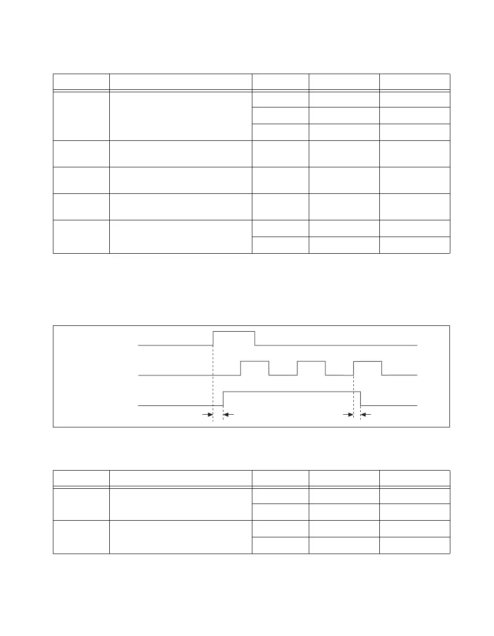
The AI timing engine also can export a signal related to the Sample Clock
called AI_Sample_In_Progress. This signal asserts with the Sample Clock
and stays asserted until after the last convert of the sample. It is useful for
external simultaneous sample and hold signal conditioning.
Figure B-17. AI_Sample_In_Progress Timing Diagram
Table B-8. Sample Clock Timing
Time Description Line Min (ns) Max (ns)
t
27
Delay to Selected Sample Clock PFI 3.5 8.9
RTSI 3.4 8.6
STAR 2.8 5.9
t
28
Selected Sample Clock Setup time
(to Sync Convert Clock Timebase)
— 1.5 —
t
29
Selected Sample Clock Hold time
(to Sync Convert Clock Timebase)
— 0 —
t
30
Sync Convert Clock Timebase to Sample
Clock
— 2.4 5.8
t
31
Sample Clock to POUT PFI 2.4 5.5
RTSI 3.2 6.8
Table B-9. AI_Sample_In_Progress Timing
Time Description Line Min (ns) Max (ns)
t
32
Sample Clock to POUT as leading edge
of AI_Sample_In_Progress
PFI 3.4 8.0
RTSI 4.2 9.2
t
33
Convert Clock to POUT as trailing edge
of AI_Sample_In_Progress
PFI 5.4 12.4
RTSI 6.2 13.6
Sample Clock
Convert Clock
POUT
t
32
t
33
 Loading...