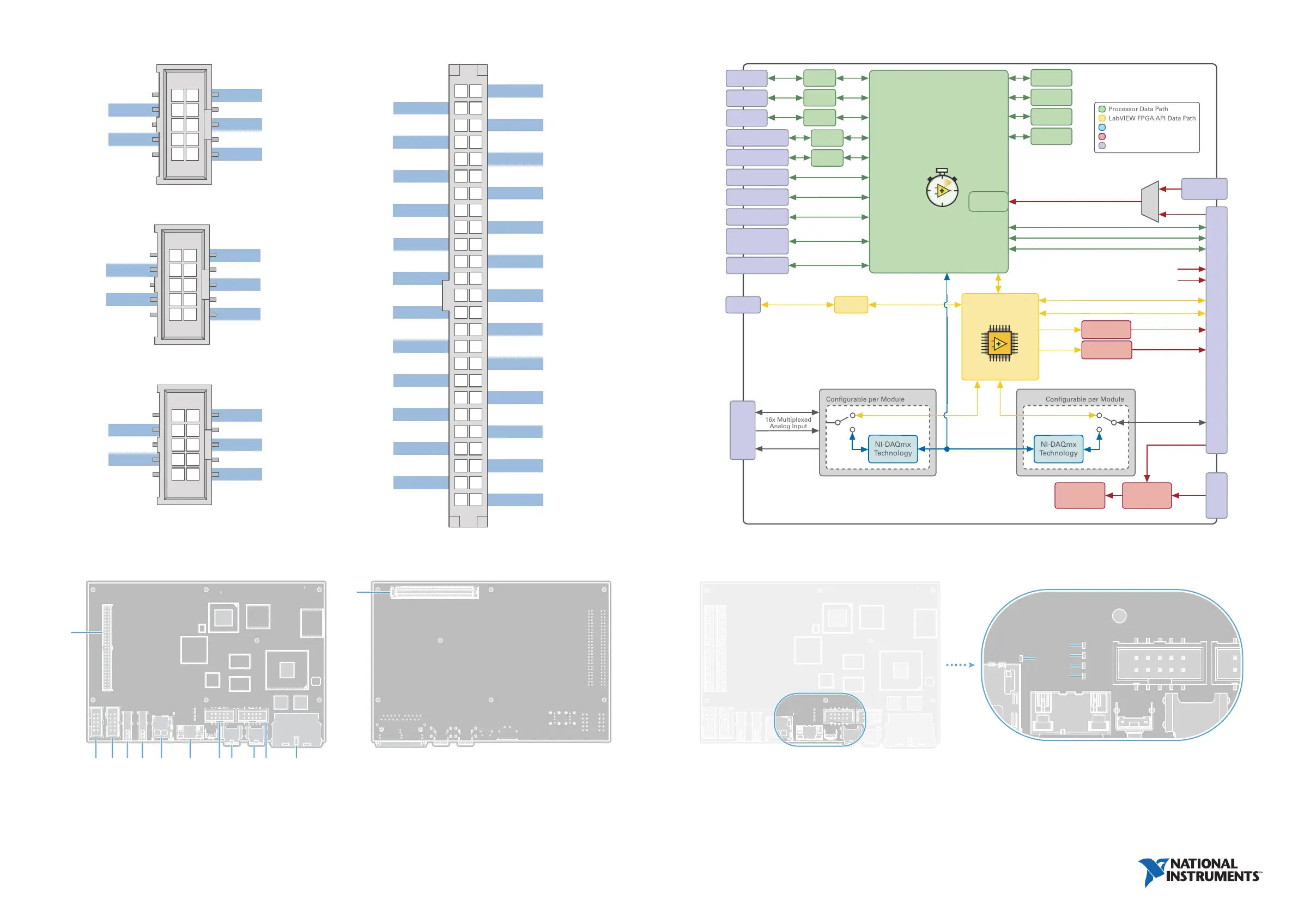
FPGA_VIO [48-95]
sbRIO-9629
Intel Atom E3845
Quad-Core
1.91 GHz Processor
UARTRS-232
UARTRS-232
UARTRS-485
High-Speed CAN
Xilinx Artix-7 200T
Real-Time
Clock
Digital I/O [0-47], SE/LVDS
Digital I/O [48-95], SE/LVDS
Temperature
Sensors
Watchdog
4 GB
eMMC Disk
2 GB
DDR3L
4x Digital I/O
(5 V Tolerant)
16x Multiplexed
Analog Input
RS-232
RS-232
Console Out
RS-485
RJ-45 TSN Gigabit
Ethernet Port
RJ-45 TSN Gigabit
Ethernet Port
USB 2.0 Host
Type-A Connector
USB 2.0 Host
Type-A Connector
USB 2.0 Device
Type-C Connector
USB 3.1 Host
Type-C Connector
with DisplayPort
MicroSD
Connector
4x Analog
Output
XCVR
XCVR
XCVR
PHY
PHY
CAN Port
Connector0 (MIO)
CAN
Controller
5 V
3.3 V
PCIe x1 Gen 2
USB 2.0
Battery Holder
(1632)
SATA 2.0
VBAT
FPGA_VIO [0-47]
2.5 V/3.3 V
Power Selector
2.5 V/3.3 V
Power Selector
9-30 VDC
Input
Power
Selection and
Protection
On-board
Power
Supplies
Power
Connector
Optional System
Power 9-30 VDC
2x C Series
Module Interface
RMC Connector
(240-pin 60x4 Searay)
LabVIEW FPGA API Data Path
NI-DAQmx API Data Path
Power Path
External Connector/Port
sbRIO-9629 Block Diagram
1
3
5
7
9
2
4
6
8
10
NC
V– (GND)
Shield
CAN_H
NC
CAN_L
NC
V– (GND)
NC
Shield
CAN Pinout
1
3
5
7
9
2
4
6
8
10
DCD
TXD
GND
RTS
RI
RXD
DTR
DSR
CTS
Shield
RS-232 Pinout (ASRL1, ASRL2)
13
2 3 4 5 6 7 98 10 11 12
1
1
2
3
4
5
1. Power LED
2. Status LED
3. User1 LED
4. User FPGA1 LED
5. SD in Use LED
1. Connector0 (MIO Port) 8. CAN port
2. RS-485 port (ASRL3) 9. USB Type-C 2.0 device port
3. RS-232 port (ASRL2) 10. USB Type C 3.1 host port
4. USB Type-A 2.0 host port 11. RS-232 serial port (ASRL1)
5. USB Type-A 2.0 host port 12. Ethernet ports
6. MicroSD port 13. RMC Connector
7. Power terminal
sbRIO-9629 LEDs
sbRIO-9629 Parts Locator Diagram
1
3
5
7
9
2
4
6
8
10
GND
NC
RXD–
NC
TXD–
NC
RXD+
NC
TXD+
Shield
RS-485 (ASRL3) Pinout
2
4
6
10
8
12
14
16
18
20
22
24
26
28
30
32
34
36
38
40
42
46
44
48
50
1
3
5
9
7
11
13
15
17
19
21
23
25
27
29
31
33
35
37
39
41
45
43
47
49
AGND
AI8
AI9
AGND
AI10
AI11
AGND
AI12
AI13
AGND
AI14
AI15
AGND
AGND
AGND
AGND
AGND
AGND
AGND
AGND
AGND
DGND
DGND
DGND
DGND
AI0
AGND
AI1
AI2
AGND
AI4
AI3
AGND
AI5
AI6
AGND
AGND
AI7
AO0
AO1
AO2
AO3
NC
NC
NC
NC
DIO0
DIO1
DIO3
DIO2
Connector0 (MIO port) Pinout
 Loading...


