78 Installing a Common Vent System
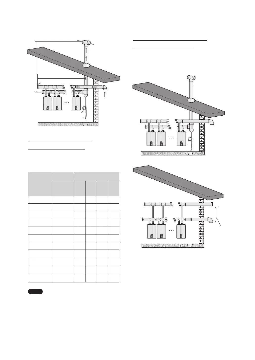
Example of a Typical Installation
(Direct & Non-Direct Vent)
The following illustration depicts an example of a
common vent system installed for a cascade system
of 12 Navien NPE heater units.
Unit 1 Unit 2 Unit 12
Unit 1 Unit 2 Unit 12
Maximum
length 20’
(6 m)
Minimum
length 36”
(91 cm)
[Direct Vent]
W
H
D
Exhaust
End Cap
Unit
1
Siphon Loop Drain Hose
Drain
Intake
Unit
2
Unit
12
Common Vent Length Table
[Total Length (L) = W + H]
Vent Length for NPE Water Heater Units
Required
Load
(Total
BTU/H)
Model Total Length (ft)
NPE-240A2/S2
D=3” D=4” D=6” D=8”
399,800 2 60 106 200
599,700 3 40 71 160
799,600 4 30 53 120
999,500 5 42 96 150
1,199,400 6 35 80 142
1,399,300 7 30 68 121
1,599,200 8 60 106
1,799,100 9 53 94
1,999,000 10 48 85
2,198,900 11 43 77
2,398,800 12 40 71
Note
●
Every 90° elbow used is equivalent to
8 linear feet (2.4 m) of vent length.
●
The maximum equivalent length of
the branch pipe from the unit to the
common vent trunk is 16 equivalent feet.
●
Branch pipe lengths are not added
to the allowable equivalent vent
lengths that are provided in the
following charts.
 Loading...