CYLINDER HEAD AND VALVE TRAIN 149
Installing the Rocker Arm Assembly
1. Place valve bridges across each set of valves.
These should be marked if removed. The
recessed holes set over the valve stems.
H08025
1
2
3
4
5
6
78 9
10 11
12
FRONT
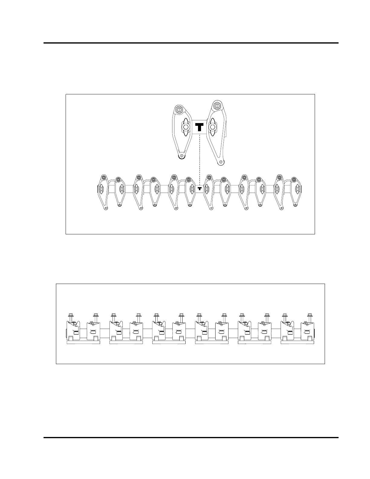
Figure 204 Rocker arm orientation
2. Align rocker arm assembly with bolts over
mounting holes and thread hand tight.
H08039
12
11
10
9
87
6
5
4
3
2
1
Figure 205 Rocker arm torque sequence
3. Torque bolts in two passes in the sequence
illustrated above and to the specified value.
a. Torque rocker arm clamp assembly bolts to 27
N·m (20 lbf·ft) for the first pass.
b. Torque rocker arm clamp assembly bolts to 37
N·m (27 lbf·ft) for the final pass.
EGES-265-2
Read all safety instructions in the "Safety Information" section of this manual before doing any procedures.
Follow all warnings, cautions, and notes.
© 2009 Navistar, Inc.
 Loading...


