5 HARD START AND NO START DIAGNOSTICS 201
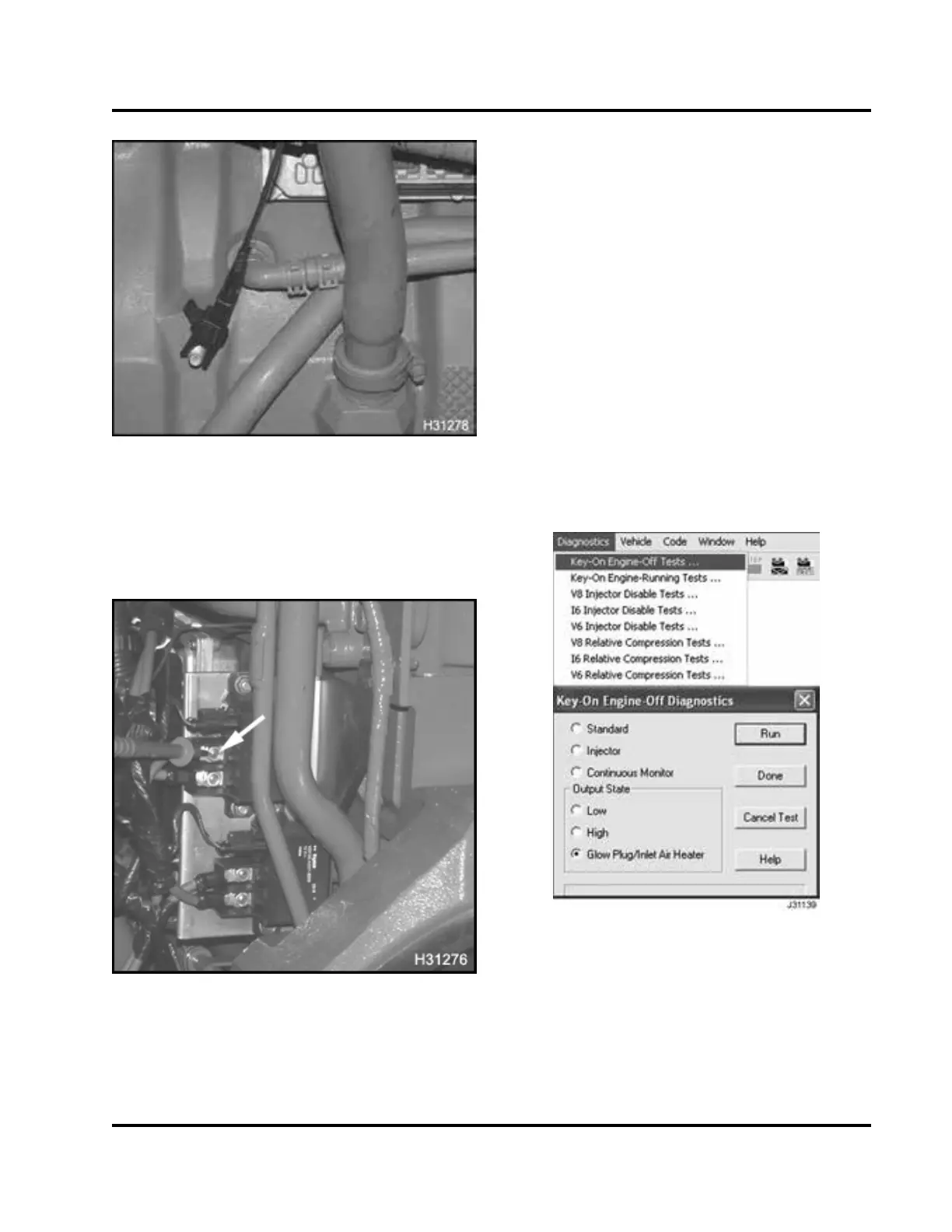
Figure 2 58 Ground terminal (left side of
crankcase)
1. Connect DMM negative lead to the ground
terminal, on the left side of crankcase or known,
good ground in the cab.
Figure 259 Relay terminal
NOTE: Engines could be wired differently, having
wiring harness connectors secured to different relay
terminals. Trace wiring harness from battery to the
relay, to be sure that the correct relay terminal is
being tested.
2. Contact DMM positive lead to relay terminal of
battery feed to relay.
3. Record results on Diagnostic F orm.
• If DMM voltage at relay t erminal is B+,
continue with step 4 and measure relay
output to element.
• If voltage of relay terminal is less than B+,
repair or replace wire from starter to relay.
Retest to verify re pair.
4. Turn the ignition s witc h to O N.
5. Contact DMM positive lead to relay output
terminal, relay to element.
Figure 260 Glow Plug/Inlet Air Heater Output
State Test
6. Select Diagnostics from the m enu bar.
7. Select Key-On Engine-Off Tests from the drop
down menu.
EGES-270-1
Read all safety instructions in the "Safety Information" section of this manual before doing any procedures.
Follow all warnings, cautions, and notes.
©August 2008 Navistar, Inc.
 Loading...


