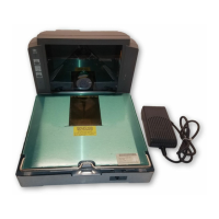
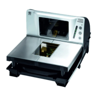
3-10 Chapter 3: Installation
c) RoutetheCheckpointcableasshownbelow.
25695
Tape may be
used to hold the
loop in place
d) Routethecableouttheleftsideoftheunit.
25696
2. Ifused,connecttheoptionalDCPowerCablefromthePowerSupplytotheDC
Powerconnector.
3. ConnecttheinterfacecabletotheScannerconnectorortheUSB+Power
Connector.
Note: Thescannercanconnecttoaseparate“POSscaleinterfacecable”through
“Port1”.Fulldetailsare
addedonthefirmwareʹsrelease.
4. Ifused,connecttheremotedisplaycabletotheRemoteDisplayconnector.
5. IftheconfigurationincludesaUSBdevice,connectittotheUSBperipheralport.
6. Ifused,connectoneendoftheSensormatic®CommunicationsCabletotheRS232
Port2connector
atthebackoftheRealScan74.TheotherendconnectstothePOS
connectorontheSensormatic®AMB9010Controller.
7. Ifused,connecttheSensormaticCoilCabletotheCoilconnectoronthe
Sensormatic®AMB9010Controller.
 Loading...