UNIVERGE SV9100 Issue 1.2
System Hardware Manual 4 - 23
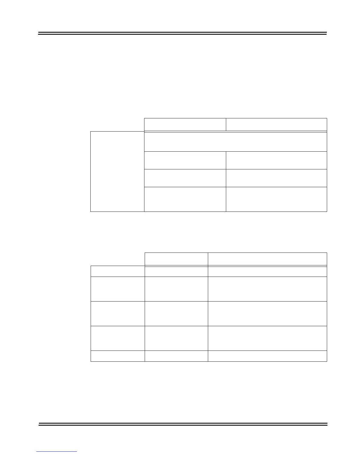
3.1.3 Switch Settings
Refer to Table 4-6 GCD-CP10 Switch Settings for system restart/
system reset and with system power on. Figure 4-3 GCD-CP10
Blade Layout on page 4-16 shows the location of the SW1 switch on
the GCD-CP10
blade.
3.1.4 LED Indications
The LEDs on the CPU indicate the following:
Table 4-6 GCD-CP10 Switch Settings
USB Memory Status Operation
Switch
S5 - Load Switch
With a system restart or a system reset while holding the SW1
switch:
When USB Memory is not
installed:
Cold Start occurs.
When USB Memory is
installed:
USB Memory contents loaded.
When an unauthorized USB
device is installed:
System does not start and an “Illegal
USB device is connected” alarm is
recorded.
Table 4-7 GCD-CP10 Switch 6 Settings
Configuration Note
SW4-1 ON Not Used
SW4-2 OFF Test Mode
ON = Test Mode
OFF = Normal
SW4-3 OFF RS232C Select
ON = Use
OFF = Not Used
SW4-4 ON Reset Configuration
ON = Normal
OFF = ICE Mode
S6 SENSE switch Not Used

 Loading...


