Issue 3.0
SV9100 System Hardware Manual 9-157
14.2 Connector Pin-Outs on COIU Blade for Power Failure Circuits
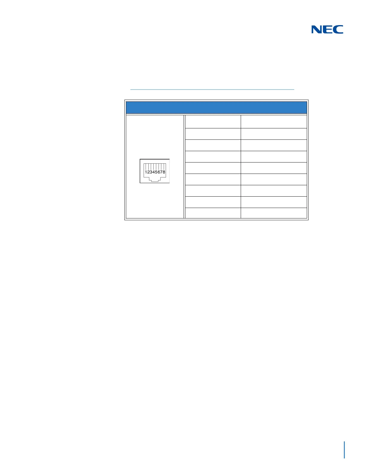
Table 9-5 RJ-61 Cable Connectorprovides the pin-outs for the RJ-61 cable
connector.
14.3 Installing the Power Failure Telephones
1. Connect an RJ-61 connector to the COIU Blade installed in the system.
2. Install a modular jack for each single line telephone supporting PF
operation. The modular jack should be within six feet of the phone.
3. For each extension, run one-pair 24 AWG station cable from the
cross-connect block to a modular jack.
4. Terminate the extension leads to GRN/RED of the modular jack. Terminate
the unused leads to the jack. Refer to Figure 9-151 Power Failure
Connector (CN3) Shown on GCD-4COTB Blade.
Table 9-5 RJ-61 Cable Connector
RJ-61 Cable Connector - CN13, SLT Interface for Power Failure
Pin No. Connection
1–
2–
3 Circuit 2 - Tip
4 Circuit 1 - Ring
5 Circuit 1 - Tip
6 Circuit 2 - Ring
7–
8–

 Loading...


