BBTS1000/1005/1021/1060/1065/1080
Installation instruction
2
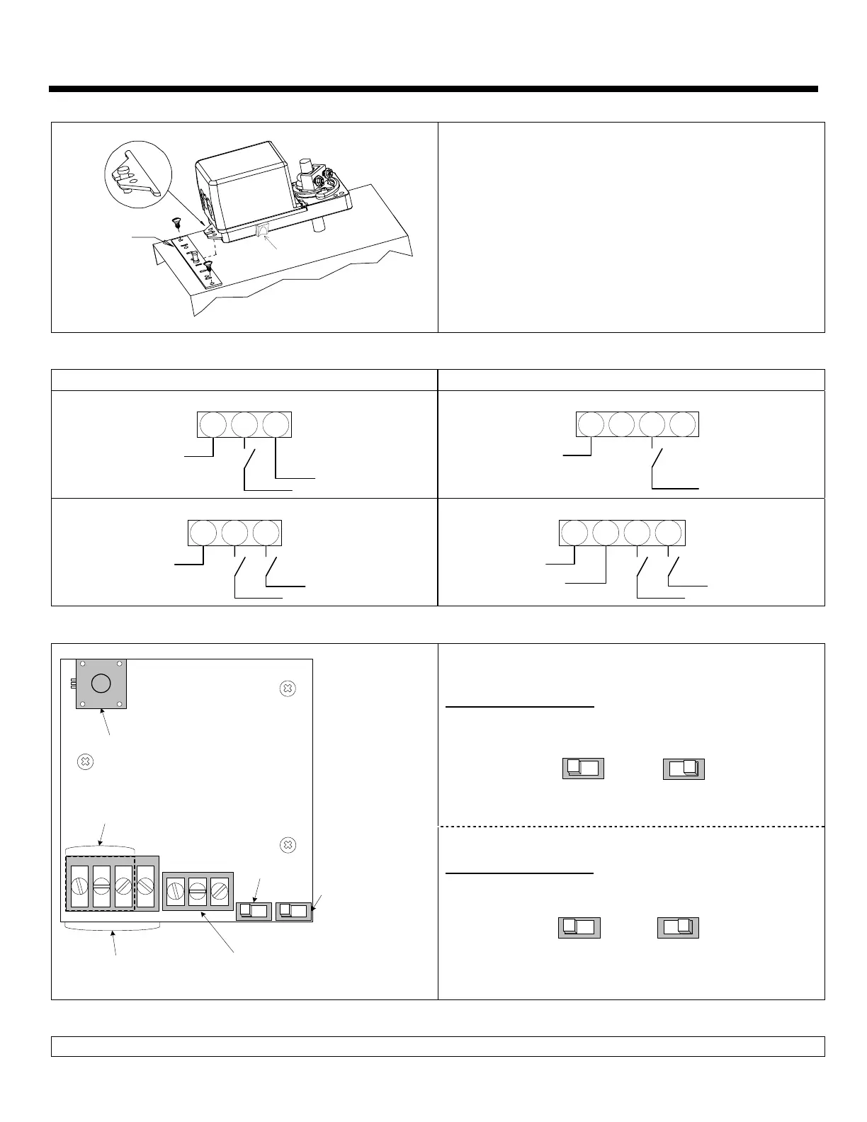
Mechanical installation
CLUTCH
MOUNTING
BRACKET
1.
Manually close the damper blades and positioned the
actuator at 0º or 90º.
2.
Slide the actuator onto the shaft.
3.
Tighten the nuts on the “U” bolt to the shaft with a 8mm
wrench to a torque of 60 in.lb. [6,7 Nm].
4.
Slide the mounting bracket under the actuator. Ensure free
movement of the slot at the base of the actuator. The
bracket pin must be placed in the mid distance of the slot.
5.
Fix the bracket to the ductwork with #8 self-tapping screws.
Wiring Diagrams
Models BBTS1000, 1005 & 1021 Models BBTS1060, 1065 & 1080
3 wire / 2 position (ON-OFF)
COMMON
DRIVE CW
SUPPLY
1 2 3
2 wire / 2 position
(ON-OFF)
COMMON
DRIVE CW
1 2 3 4
3 wire / 3 point floating
COMMON
DRIVE CW
DRIVE CCW
1 2 3
4 wire / 3 point floating
COMMON
SUPPLY
DRIVE CW
DRIVE CCW
1 2 3 4
PC Board
Dip switch settings
Rotation direction (SW1)
CW
(0 to 90º)
CCW
(90 to 0º)
SW2
Potentiometer
Only on model 1005, 1065
BT060VAV
1 2 3 4
Feedback or switches terminal
Only on model 1005, 1021,
1065 & 1080
Rotation
direction
6 7 8
Fail safe direction
Only on model
1060, 1065 & 1080
SW1
Terminal 4 pins
Only on model
1060, 1065 & 1080
Terminal 3 pins
Only on model
1000, 1005 & 1021
Fail safe direction (SW2)
Fail safe
return at 0º
Fail safe
return at 90º
Stroke adjustment
To adjust the stroke, move the adjustment screws at the desired position.
 Loading...