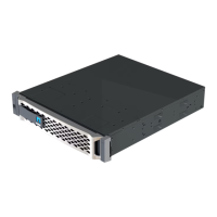
The controller module begins to boot as soon as it is fully seated in the chassis. Be prepared to
interrupt the boot process.
The controller module should be fully inserted and flush with the edges of the chassis.
5. Repeat the preceding steps to install the second controller into the new chassis.
Complete the restoration and replacement process - AFF A250
You must verify the HA state of the chassis, run diagnostics, and return the failed part to
NetApp, as described in the RMA instructions shipped with the kit.
Step 1: Verify and set the HA state of the chassis
You must verify the HA state of the chassis, and, if necessary, update the state to match your system
configuration.
1. In Maintenance mode, from either controller module, display the HA state of the local controller module and
chassis:
ha-config show
The HA state should be the same for all components.
2. If the displayed system state for the chassis does not match your system configuration:
a.
Set the HA state for the chassis:
ha-config modify chassis HA-state
The value for HA-state can be one of the following:
▪
ha
▪
mcc
▪
mccip
▪
non-ha
b.
Confirm that the setting has changed:
ha-config show
3. If you have not already done so, recable the rest of your system.
4. Reinstall the bezel on the front of the system.
Step 2: Run diagnostics
After you have replaced a component in your system, you should run diagnostic tests on that component.
Your system must be at the LOADER prompt to start diagnostics.
All commands in the diagnostic procedures are issued from the controller where the component is being
replaced.
1.
If the controller to be serviced is not at the LOADER prompt, reboot the controller:
system node halt
-node node_name
After you issue the command, you should wait until the system stops at the LOADER prompt.
2. At the LOADER prompt, access the special drivers specifically designed for system-level diagnostics to
262

 Loading...