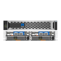
Step 11: Install the power supplies
Installing the power supplies when replacing a chassis involves installing the power
supplies into the replacement chassis, and connecting to the power source.
1. If you are not already grounded, properly ground yourself.
2. Using both hands, support and align the edges of the power supply with the opening in the system chassis,
and then gently push the power supply into the chassis until it locks into place.
The power supplies are keyed and can only be installed one way.
Do not use excessive force when sliding the power supply into the system. You can damage
the connector.
3. Reconnect the power cable and secure it to the power supply using the power cable locking mechanism.
Only connect the power cable to the power supply. Do not connect the power cable to a
power source at this time.
4. Repeat the preceding steps for any remaining power supplies.
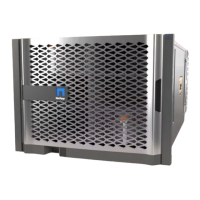
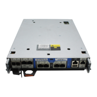
Step 12: Install the controller
After you install the controller module and any other components into the new chassis,
boot it to a state where you can run the interconnect diagnostic test.
1. If you are not already grounded, properly ground yourself.
2. Align the end of the controller module with the opening in the chassis, and then gently push the controller
module halfway into the system.
Do not completely insert the controller module in the chassis until instructed to do so.
3. Recable the console to the controller module, and then reconnect the management port.
4. Connect the power supplies to different power sources, and then turn them on.
5. With the cam handle in the open position, slide the controller module into the chassis and firmly push the
controller module in until it meets the midplane and is fully seated, and then close the cam handle until it
clicks into the locked position.
Do not use excessive force when sliding the controller module into the chassis; you might
damage the connectors.
The controller module begins to boot as soon as it is fully seated in the chassis.
6. Repeat the preceding steps to install the second controller into the new chassis.
7. Boot each node to Maintenance mode:
a.
As each node starts the booting, press
Ctrl-C to interrupt the boot process when you see the
message Press Ctrl-C for Boot Menu.
48
 Loading...