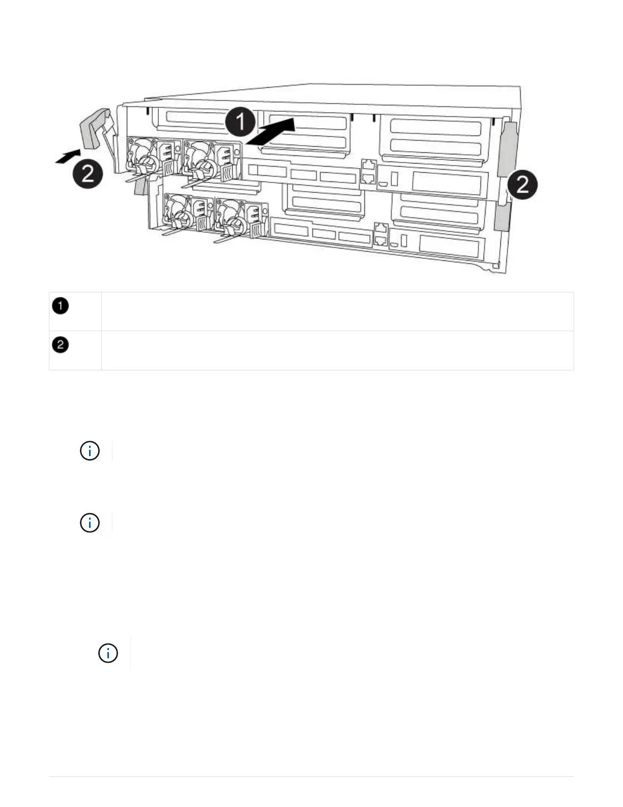
Controller module
Controller locking latches
1. If you have not already done so, close the air duct.
2. Align the end of the controller module with the opening in the chassis, and then gently push the controller
module halfway into the system.
Do not completely insert the controller module in the chassis until instructed to do so.
3. Cable the management and console ports only, so that you can access the system to perform the tasks in
the following sections.
You will connect the rest of the cables to the controller module later in this procedure.
4. Complete the installation of the controller module:
a. Plug the power cord into the power supply, reinstall the power cable locking collar, and then connect
the power supply to the power source.
b. Using the locking latches, firmly push the controller module into the chassis until the locking latches
begin to rise.
Do not use excessive force when sliding the controller module into the chassis to avoid
damaging the connectors.
c. Fully seat the controller module in the chassis by rotating the locking latches upward, tilting them so
that they clear the locking pins, gently push the controller all the way in, and then lower the locking
latches into the locked position.
The controller module begins to boot as soon as it is fully seated in the chassis. Be prepared to
67