Mount the switch on a wall
We recommend that you use the wall-mount screws that came with the switch.
1. Locate the two mounting holes on the bottom panel of the switch.
2. Mark and drill two mounting holes in the wall.
3. The two mounting holes must be 3.19 in. (80 mm) apart, center-to-center.
Insert the supplied anchors into the wall and tighten the screws with a No. 2
Phillips screwdriver.
Leave about 0.12 in. (4 mm) of each screw protruding from the wall so that
you can insert the screw heads into the holes on the bottom panel.
NOTE: The screws are 0.25 in. (6 mm) in diameter, 1.1 in. (27 mm) in length.
Specications
Specication Description
Network interface RJ-45 connector for 1000BASE-T, 100BASE-TX, or
10BASE-T
Network cable Category 5 (Cat 5) or higher rated Ethernet cable
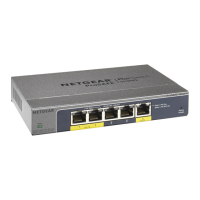
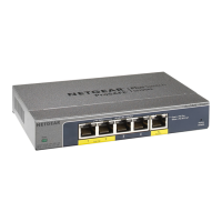
Ports 5 total. Ports 1-4 can provide PoE+; Port 5 is an uplink port.
Power adapter Model GS105P: 54V @ 1.25A DC input
Model GS105PP: 54V @ 1.66A DC input
Power consumption Model GS105P: 67.5W maximum; 1.02W standby
Model GS105PP: 90.0W maximum; 1.01W standby
PoE power budget Model GS105P: 30W maximum per PoE+ port with a total
PoE power budget of 63W for the switch
Model GS105PP: 30W maximum per PoE+ port with a total
PoE power budget of 83W for the switch
Dimensions (W x D x H) 6.2 x 4.0 x 1.1 in. (158 x 101 x 27 mm)
Weight 0.88 lb (0.40 kg)
Operating temperature 32–104°F (0–40°C)
Operating humidity 10%–90% relative humidity, noncondensing

 Loading...