PART1
ENGINE SYSTEMS
Chapter
1
DIESEL
ENGINES
Section
A DESCRIPTION
AND
OPERATION
Page
1
B FAULT FINDING
4
C
D
E
DISASSEMBLY
AND
OVERHAUL
COMPRESSION
TEST
SPECIFICATIONS
8
37
38
48
F
SPECIAL
TOOLS
A.
DIESEL
ENGINE
-
DESCRIPTION
AND
OPERATION
MODEL
5640
6640
No
of
Cylinders
4 4
BORE
(ins.)
4.4
4.4
(mm)
111.8
111.8
STROKE
(ins.)
4.4
5.0
(mm).
111.8
127.0
DISPLACEMENT
(cu. in.)
268
304
(cu. cm.)
4393
4983
(T) =
Turbocharger
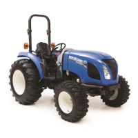
This chapter describes the overhaul and re-
pair
of
the
new
series, direct injection diesel
engines.
These engines are available in 4
or
6 cylinder
naturally aspirated forms, with the 4 cylinder
also being available
in
turbocharged form.
As these engines are of similar design and
service procedures are common throughout
the range. The 4 cylinder engines have a de-
sign difference
in
that they are fitted with a dy-
namic balancer assembly.
All engines feature cross flow cylinder heads,
with the inlet
and
exhaust manifolds on oppo-
site sides
of
the cylinder head. The fuel and
air combustion process, takes place
in
the
specially designed bowl in the crown
of
the
pistons.
CYLINDER HEAD ASSEMBLY
The
cylinder head incorporates valves and
springs with the valve rocker arm shaft as-
sembly
bolted to the cylinder block through
the cylinder head. Cylinder head retaining
bolts are evenly spaced with a six point pat-
tern around each cylinder, this ensures an
even clamping load across the cylinder head
area.
The
intake and exhaust manifolds are bolted
to the head.
The
intake manifold is mounted
1
7740
(T)
7840
8240
8340
4
6 6 6
4.4
4.4
4.4
4.4
111.8
111.8
111.8
111.8
5.0
4.4
5.0 5.0
127.0 111.8 127.0
127.0
304
401
456
456
4983
6570
7472
7472
on the right hand side
of
the
engine with the
diesel injectors mounted outside the rocker
cover. The exhaust manifold is mounted on
the left hand side
of
the engine,
water
outlet
connections and thermostat being attached
to the front
of
the cylinder block directly be-
hind the radiator.
Valve guides are integral in the cylinder head
and valves with oversize stems are available
in
service. Special replaceable
cast
alloy
valve seats are pressed into each valve port
during manufacture, with oversize valve
seats also available
in
service.
All valves are fitted with positive valve rota-
tors, with both Intake and exhaust valves us-
ing umbrella type oil seals. Valve lash is main-
tained
by
adjustment
of
the self locking ad-
justing screw, mounted
in
each
of
the rocker
arms.
CAMSHAFT ASSEMBLY
The camshaft runs
in
replaceable bearings,
with 3 fitted in the 4 cylinder and 5 fitted in the
6 cylinder. The camshaft drive
gear
is in mesh
with, and driven
by
the camshaft idler
gear
and crankshaft timing gear.
Camshaft end thrust is controlled
by
a thrust
plate bolted to the block and located between
the camshaft
gear
and the front camshaft
journal.
A helical
gear
is mounted on the rear
of
the
camshaft and drives the engine oil lubrication
pump
mounted forward
of
the flywheel.

 Loading...