AN-179
Built-in receiver, On/Off
TECHNICAL DATA
AN-179
Power source 220-240 V~50 Hz
Max. charge 2500 W R
Frequency Z-Wave (868.42 MHz)
Range up to 30 m
Power consumption < 1 W (standby)
IP rating Indoor use
Dimensions (W x H x D) 43 x 42 x 16 mm
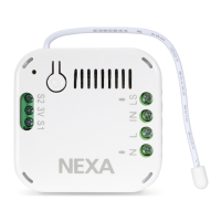
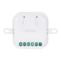
Built-in receiver for permanent installation. Small, compact size
for placing in a junction box or switchbox. Can be connected to
existing switch. The receiver needs both phase and neutral. The
receiver is fully compatible with the Z-Wave Plus standard.
SAFETY
Read through the entire instruction first. Engage a professional if so
required. Nexa cannot be held liable if the product is used for any
purpose other than the one for which it is designed, or if there is
failure to comply with the instruction.
Never connect bulbs or equipment exceeding the receiver’s
maximum stated load – this may lead to faults, short-circuiting or
fire. Do not attempt to repair the product.
The product contains no repairable parts.
INSTALLATION
Make sure that the conductors are powered down by turning
off the power in the distribution box.
Connect Phase to L and IN, Load/Ignition wire to LS and Zero
Conductor to N.
AN-179 can be connected to power switches, even momentary
switches, for control, also see wiring diagram.
Please note that switches connected to AN-179 must be potential
free, i.e. fully insulated from 230 V.
CONNECT TO A Z-WAVE NETWORK
Auto-inclusion:
When AN-179 is powered up for the first time and a NODE ID has
not been assigned, it starts in auto-inclusion mode.
1. Put the Z-Wave controller in inclusion mode (see the controller's manual)
2. Connect AN-179 to voltage and the unit is included.
Manual Inclusion:
1. Put the Z-Wave controller in inclusion mode (see the controller's manual)
2. Press 3 times on the Link button within 1.5 seconds
Exclusion:
1. Put the Z-Wave controller in exclusion mode (see the controller's manual)
2. Press 3 times on the Link button within 1.5 seconds.
Restore to factory settings:
1. Press 3 times on the Link button within 1.5 seconds.
2. Within 1 second after step 1 above, press and hold down the link
button until the LED goes out, approx. 5 seconds.
3. Node ID is deleted and the unit restored to factory settings.
USE
Control using Z-Wave controller: Consult the manual for your Z-Wave
controller for information about how to control your receiver.
SAFETY AND INFORMATION
ENGLISH
NEXA AB, DATAVÄGEN 37B, 436 32 ASKIM, SWEDEN
info@nexa.se | www.nexa.se
LOAD MAX POWER
Incandescent bulbs % Resistive loads (230 V) 2500W /220-240 V
Halogen lights (230 V) 1200W / 220-240 V
LED & Low energy bulbs (230 V)
320 W / 220-240 V (40 W x 8)
Connections for power switch
Connections for voltage
LED display
Link button
N
L
N
L
Range indoors: up to 30 m (optimal conditions). The range is
very dependent on the local conditions, for example, if there
are metals in the vicinity. For example, the thin metal coating in
energy glass with low emissivity has a negative influence on the
range of the radio signals. There may be restrictions on the use of
the unit outside the EU. If appropriate, you should check that the
unit complies with local regulations.
Max load: Never connect lights or equipment that exceed the
receiver's maximum load. This could lead to faults, short-
circuiting or fire.
Life-support equipment: Never use Nexa's products with life-
support equipment or other devices where faults or interference
could have life-threatening consequences.
Interference: All wireless units can suffer from interference that
can affect the performance and range.
For this reason, the minimum distance between two receivers
should be at least 50 cm
Repair: Do not attempt to repair the product. It does not contain
any repairable parts.
Waterproofing: The product is not waterproof. Make sure it is dry
at all times. Damp causes the electronics inside to corrode and this
could lead to short-circuiting, faults and a risk for electric shocks.
Cleaning: Clean the product with a dry cloth. Do not use
chemicals, solvents or strong cleaning agents.
Environment: Do not expose the product to intense heat or cold,
because it could damage or shorten the service life of the
electric circuits.
WIRING DIAGRAM
Z-WAVE PLUS INFO
AGI (ASSOCIATION GROUP INFORMATION) TABLE
VERSION
MANUFACTURER
Role Type Node Typer Installer Icon User Icon
Slave Always On Z-Wave Plus node
On/Off Power
Switch
On/Off Power
Switch
Parameter
Number
Size Range Default
3 1 1/0 1:remember(0: do not remember)
Parameter
Number
Size Range Default
4 1 1/0
0: Bistable switch
1: Momentary switch
Group Profile
Command Class & Command
(List) N bytes
Group Name (UTF-8)
1 General:NA
Binary Switch Report,
Notification Report,
Device Reset Locally Notification
Lifeline
2 Control:Key1 Basic Set
On/Off control
Button 1
Protocol Library 3 (Slave_Enhance_232_Library
Protocol Version 3.95 (6.51.02)
Manufacturer ID Product Type Product ID
0x0060 0x0004 0x0008
BASIC
• Basic Get: Inquire about the status of the device.
• Basic Report: Report the status of the device.
• Basic Set: Set the status of the device.
NOTIFICATION
The device will send notifications (Notification Type =0x08, Event =
0x01) upon being powered on.
COMMAND CLASSES
The module supports Command Classes including -
• COMMAND_CLASS_ZWAVEPLUS_INFO_V2
• COMMAND_CLASS_VERSION_V2
• COMMAND_CLASS_MANUFACTURER_SPECIFIC_V2
• COMMAND_CLASS_DEVICE_RESET_LOCALLY_V1
• COMMAND_CLASS_ASSOCIATION_V2
• COMMAND_CLASS_ASSOCIATION_GRP_INFO_V1
• COMMAND_CLASS_POWERLEVEL_V1
• COMMAND_CLASS_BASIC_V1
• COMMAND_CLASS_NOTIFICATION_V4
• COMMAND_CLASS_CONFIGURATION_V1
• COMMAND_CLASS_SWITCH_BINARY_V1
• COMMAND_CLASS_SWITCH_ALL_V1
• COMMAND_CLASS_FIRMWARE_UPDATE_MD_V2
Remember the last status:
Switch 1 type:
Parameter
Number
Size Range Default
1 2 0-99, 255 (0xFF) 255 (0xFF)
Parameter
Number
Size Range Default
2 1 3-25 (seconds) 3
The delaying time to report to Group 1
CONFIGURATION
The configurable values are as following:
Basic Set Command Value