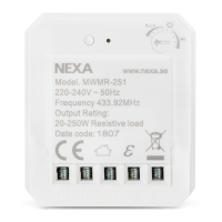
MWMR-251
BUILT-IN DIMMER
Built-in dimmer for permanent installation. Small, compact size with
input for a retractive switch (230V). Adjustable between leading
edge dimming and trailing edge dimming, plus minimum dimmer
level. The receiver needs both phase and neutral.
SAFETY
Read through the entire instruction first. Engage a professional if so
required. Nexa cannot be held liable if the product is used for any
purpose other than the one for which it is designed, or if there is
failure to comply with the instruction.
Never connect bulbs or equipment exceeding the receiver’s
maximum stated load – this may lead to faults, short-circuiting or
fire.
Do not attempt to repair the product. The product contains no
repairable parts.
INSTALLATION
Make sure that the conductors are powered down by turning off the
power in the distribution box.
Connect Phase to L, Charge/Bridgewire to L
and Neutral
conductor to N – see also the wiring diagram.
LINKING
With X-Link & switch connected to S-input
1. Power up MWMR-251.
2. Click the power switch three times within 1.5 seconds to
enable training mode. The connected light flashes 3 times as
confirmation that training mode is active.
3. Press the “ON” button for the selected channel on a System
Nexa remote control/transmitter(?) within 6 seconds.
Without X-Link
1. Power up MWMR-251.
2. Press the training button, the LED indicator starts to flash.
3. Press the “ON” button for the selected channel on a System
Nexa remote control within 6 seconds.
LINKING CONFIRMATION
The LED indicator on the receiver flashes rapidly.
ENGLISH
TECHNICAL DATA
Declaration of conformity is available at www.nexa.se
THIS PRODUCT SUPPORTS SMART MODE.
Devices that support Smart Mode can save up to 3 different
favourite scenarios, and these can be activated easily using a Nexa
Smart Mode transmitter.
NEXA AB, DATAVÄGEN 37B, 436 32 ASKIM, SWEDEN
info@nexa.se | www.nexa.se
DELETING A MEMORY SLOT
1. Power up MWMR-251.
2. Press the learn button, the LED indicator starts to flash.
3. Press the “OFF” button for the selected channel on the remote
control within 12 seconds.
CONFIRMATION OF DELETION
The LED indicator on the receiver flashes rapidly.
DELETING ALL MEMOMRY SLOTS
1. Power up MWMR-251.
2. Press and hold down the learn button for 6 seconds
, the LED
indicator starts to flash.
3. Release the learn button and then press it again briefly.
All memory slots are now deleted.
MEMORY
Every MWMR-251 receiver has 32 memory slots. When memory slot
32 is occupied, slot 1 is overwritten during programming.
DIMMER SETTINGS
MWMR-251 is supplied set for leading edge dimming and can be
reset to trailing edge dimming.
Selection of an appropriate setting is dependent on the type of
charge to be connected – see the table below.
Contact the place of purchase for your luminaire/light if you are not
sure what type of load to be set.
SETTING LEADING EDGE DIMMING
1. Rotate the adjustment knob counterclockwise to end position R,
L, C. The LED indicator flashes once.
2. Rotate the adjustment knob slowly clockwise to adjust the
minimum dimming level.
SETTING TRAILING EDGE DIMMING
1. Rotate the adjustment knob clockwise to end position RC. The
LED indicator flashes once.
2. Rotate the adjustment knob slowly counterclockwise to adjust
the minimum dimming level.
SAFETY AND INFORMATION
Indoor range: up to 30 m (optimal conditions). The range is strongly
dependent on local conditions, such as the presence of metals. For
example, the thin metal coating in Low-emissivity (Low-E) glass has
a negative impact on the range of radio signals.
There may be restrictions on the use of this device outside the EU. If
applicable, check whether this device complies with local directives.
Maximum load: Never connect lights or equipment that exceed
the maximum load of the receiver, as it can result in defects, a short
circuit or fire.
Life-support: Never use Nexa products for life-support systems or
other applications in which equipment malfunctions can have life-
threatening consequences.
Interference: All wireless devices may be subject to interference,
which could affect performance. The minimum distance between 2
receivers should be at least 50 cm.
Repairing: Do not attempt to repair this product. There are no user-
serviceable parts inside.
Water-resistance: This product is not water-resistant. Keep it dry.
Moisture will corrode the inner electronics and can result in a short
circuit, defects and shock hazard.
Cleaning: Use a dry cloth to clean this product. Do not use harsh
chemicals, cleaning solvents, or strong detergents.
Environment: Do not expose the product to excessive heat or cold,
as it can damage or shorten the life of electronic circuit boards.
N N
N
L S
S =
=
=
=
L
L
L
N
N
L
N L S L
WIRING DIAGRAM
MWMR-251
Power supply 220-240 V~50 Hz
Max. load 20–250 W R/RC / 40–250 W RL
Max. load LED 3–120 W LED
Frequency System Nexa (433,92 MHz)
Range up to 30 m
Memory slots 32
Power consumption < 1 W (standby)
IP rating Indoor use
Size 40 x 45 x 15 mm
LOAD SETTING OUTPUT
Halogen lamps and bulbs Trailing edge 25-250W /220-240V W RL
Electronic transformers Trailing edge 20-250W / 220-240V
Dimmable LED and
low-energy bulbs
Trailing edge 3-120W / 220-240V
Conventional transformers Leading edge 40-250W / 220-240V
NO DIMMING, ON/OFF FUNCTION ONLY
Rotate the adjustment knob to the “ON/OFF” position. The LED
indicator flashes rapidly and the connected light is dimmed to the
maximum level.
CONTROL
The receiver can be controlled in a number of ways.
1. With a trained System Nexa remote control
2. With other trained System Nexa transmitters
3. With a retractive switch
4. With a Nexa Bridge
CONTROLLING THE RECEIVER WITH A RETRACTIVE SWITCH
A brief press on a retractive switch switches the connected charge
on or off. Press and hold down the retractive switch to increase or
reduce the dimming level.
Note: MWMR-251 is a universal type dimmer.
To avoid damage to the receiver ithas to be set up for the type
of load that is connected to it, see ”Dimmer settings” for more
information.
Learn button
LED indicator
Adjustment knob for leading,
trailing edge dimming and
minimum dimming level
Neutral
Input for retractive
switch (220-240V)
Phase
Controlled voltage