Do you have a question about the NI PXIe-1095 and is the answer not in the manual?
Details chassis bandwidth, performance, and cooling requirements for instrumentation.
Highlights chassis reliability aspects like temperature range, monitoring, and power supplies.
Explains multi-chassis support, timing slots, and clock routing for synchronization.
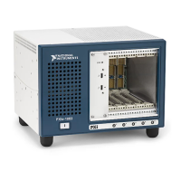
Identifies and describes key components on the front panel of the PXIe-1095 chassis.
Details rear panel connections and lists optional equipment for the chassis.
Details pin assignments for System Controller Slots XP1, XP2, XP3, and XP4.
Details pin assignments for System Timing Slots TP1, TP2, XP3, and XP4.
Details pin assignments for Hybrid Slots P1, XP3, and XP4.
Describes the states and meanings of the front panel LEDs.
Describes the states and meanings of the rear panel power supply LED.
Explains the function and states of the backplane DIP switches for fan and inhibit modes.
Discusses compatibility of the PXIe-1095 chassis with CompactPCI devices.
Details the system controller slot and hybrid/PXI Express peripheral slots.
Lists the types of PXI Express and CompactPCI Express modules supported by the slots.
Describes supported modules, differential pairs, and clock/trigger connectivity for the timing slot.
Illustrates the architecture for PXI_CLK10, PXIe_CLK100, and PXIe_SYNC100 signals.
Explains the OCXO, 10 MHz input, and output reference capabilities.
Provides instructions for unpacking, inspecting, and initial setup requirements.
Covers cautions, warnings, hazardous voltages, and protective earth wiring.
Details the importance of maintaining sufficient clearance for proper chassis cooling.
Specifies chassis cooling clearances and identifies vent locations.
Covers ambient temp definition, filler panels, slot blockers, and rack mounting for cooling.
Step-by-step instructions for connecting the chassis to earth ground.
Explains how to power on the chassis and place it in standby mode using the inhibit switch.
Configures chassis inhibit modes via software or DIP switch.
Configures fan modes, cooling profiles, and fan speed selection.
Details the pinout for the high-density trigger connector.
Shows the 15-pin connector pinout and how to check chassis voltage levels.
Details acceptable voltage ranges and the fault signal definition for chassis monitoring.
Lists and describes the signals for the rear USB 3.0 Type A port.
Configures chassis settings, including triggers, inhibit mode, and fan settings via MAX.
Details trigger configuration, bus routing, and dynamic/static reservation in MAX.
Explains the role of chassis.ini and pxisys.ini files for system configuration.
Covers cleaning intervals, preparation, and static discharge precautions.
Details interior and exterior cleaning methods for the chassis.
Step-by-step guide for removing and installing the chassis power supply.
Procedure for removing and installing the rear module fan assembly.
Procedure for removing and installing the side fan assembly.
Explains the factory calibration process for setting the OCXO frequency.