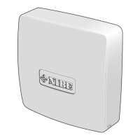
Electrical connection
CONNECTING COMMUNICATION
NOTE
All electrical connections must be carried out
by an authorised electrician.
Electrical installation and wiring must be carried
out in accordance with the stipulations in force.
The heat pump must not be powered when
installing EME 20.
• To prevent interference, sensor cables to external
connections must not be laid close to high voltage
cables.
• The minimum area of communication and sensor
cables to external connections must be 0.5 mm² up
to 50 m, for example EKKX, LiYY or equivalent.
• EME 20 restarts after a power failure.
CABLE LOCK
Use a suitable tool to release/lock cables in terminal
blocks.
CONNECTING TO INVERTER
RS-485 - COMMUNICATION
Connect the cables to the converter according to the
diagram below.
NOTE
The front cover on the inverter must not be
opened. Connection must take place via the
intended communication input under the invert-
er. Use the enclosed terminal block supplied
with the inverter. Note how the cables are
connected in the terminal block!
PVI 30-20
PVI 10-3
PVI 20-XX
PVI 10/20
FunctionConnection
RS485 + (B)1
RS485 - (A)2
Not used3
Not used4
RS485 + (B)5
RS485 - (A)6
11EME 20 S-series | GB
S

 Loading...