Chapter
4
Assembly
2.
3.
4.
5.
fl
Wnen using
phase
contrast microscopy
lf
you
also wish to
perform phase
contrast microscopy, install the
phase
conlrast obiectives and the
condenser cassettes
for
phase
contrasl observation
that correspond
to the condenser lenses to be used, as
described in the microscope instruction manual.
Before beginning observation,
be sure
to center the
annular
diaphragm.
(Refer
to the
microscope instruction
manual.)
The
assembly
procedure
is now complete.
lf
you
require
a very
precise
vibraîion direction adjustment,
proceed
with step 9.
lil
Optical
System
Direction Adiustment
(Adiustment
of vibration direction)
To assure
thal DIC
images
can be observed at optimum
contrast,
the vibration
direction of lhe
polarizer
and
analyzer must be adjusted correctly.
1. Focus
and center lhe system condenser as
describ€d in the microscope instruction manual.
.
Bring
the A
(empty)
cassette into
the optical
path.
When
using the condenser slider, remove
the condenser cassette that is in the
optical
path
so the
slider
is
empty.
.
Bemove the
polarizer,
analyzer, and objective
DIC
prism
from the optical
path.
.
When using a high NA
condenser:
In
order to
focus
the field aperture
diaphragm image on the specimen surface,
and
in
order to avoid
striking lhe spgcimen with the condenser
lens, move the
condenser
lens
slightly closer than
the
subiect distance for
each condenser lens,
and then bring the specimen into focus
while raising the
condonser lens. When
using a oil-immersion
type condenser, also check
page
g.
Remove
the objective
DIC
prism
that ls located
directly below the
4Ox
obiective.
Swilch to
the
4Ox
objective
and bring the specimen
into focus.
Move
the stage so
that the specimen moves
oui
of the
viewfield. In its
place,
bring an almost dust-free
area
into the viewfield.
(There
musî be no
dust in
the
whole viewfield.)
Turn
the Bertrand lens in/out
lever to the
[Bl
position
to bring the Bertrand lens into
the optical
path
so
that the obiective's
€xit
pupil
(the
bright
circle)
can be observed.
(lf
your
eyepiece tube has no Bertrand
lens in/out
lever, install
a cenlering telescope instead
of an eyepiece and rotate its
eyepiece
part
to
focus
on
the
obiective's
exit
pupil.)
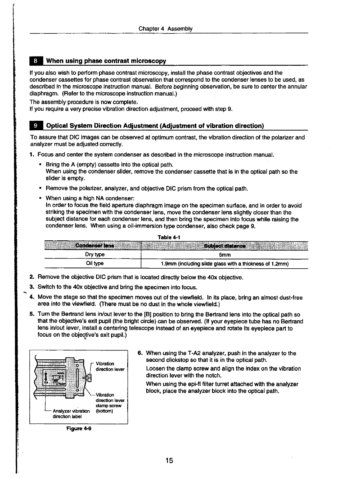
Vibration
dirgcton lgvgr
Vlbradon
dirgclion lgver
damp scf€r',
(bottom)
Figurc 4-9
6. When
using the
T-A2
analyzer,
push
in the analyzer
to
the
second
clickstop so that
it is in
the optical
path.
Loosen
the clamp screw and align the index on
the
vibration
direction lever with the notch.
When
using the epi-fl
filter
turret attached with the analyzer
block,
place
the analyzer block
into
the optical
path.
Teble {-1
f .gmm
(including
slide
glass
with a thid(rless of f .2mm)
15
 Loading...