Safety Precautions
To
ensure
proper operation,
read
t
his
manual thor-
oughly
before
using
this
product. After
read
i
ng,
be
sure
to
keep
it where
it
can
be
seen
by
all
those who
use
the product.
Notice
for
Customers
in
EuroP.e
CAUTION
RISK
OF
EXPLOS
I
ON
IF
BATIERY
IS
REPLACED
BY
AN
IN
-
COR
R
ECTTYPE.
DI
SPOSE
OF
USED
BATIERIES
ACCORD
-
ING
TO
THE
INSTRUCT
I
ONS.
Th
is
symbol
indicates
that
el
ectrical
and
el
ec-
)t
tronic
equ
rp
ment
is
to
be
collected
separately.
The
following
app
ly
only
to
users
in
European
countr
i
es
:
-
•
This
pr
oduct
is
designa
t
ed
for
separate
collection
at
an
appropr
ia
te
collect
i
on
point.
Do
no
t
dispose
of
as
house
-
hold
waste
.
•
Separate
collection
and
recycling
he
l
ps
conserve
natural
resou
r
ces
and
prevent
negative
consequences
for
hu
-
man
health
and
the
env
i
ronment
that
mrght
resu
lt
from
i
ncorrect
disposal.
• F
or
more
informatron,
contact
the
re
t
ailer
or
the
loc
al
au
-
thorities
in
charge
of
waste
management.
Notice
for
Custome
rs
in
the
U.S.A
.
F
edera
l Com
munication
s C
omm
i
ss
i
on
(FC(}
R
adio
F
req
uen
cy
I
nt
erf
er
-
en
ce
St
a
te
me
nt
T
his
equipment
has
been
tested
and
found
to
comply
w
it
h
the
li
mits
for
a
Class
B di
gital
dev
ic
e,
pursuant
to
Part
15
of
the
FCC
ru
les.
T
hese
li
mits
are
designed
to
provide
reasonable
protect
i
on
against
harmful
interference
in a
residentia
l
installa
t
ion.
T
his
equipment
generates,
uses,
and
can
radiate
radio
frequency
energy
and,
if
not
installed
and
used
in
accordance
with
the
instructions,
may
cause
harmful
interference
to
radio
communications.
However,
there
is
no
guarantee
that
interference
wil
l
not
occur
in
a
particular
i
nstal
l
ation.
If
th
is
equipment
d
oes
cause
h
arm
-
ful
interference
to
r
adio
or
television
reception,
which
can
be
determined
by
t
urning
the
equrpment
off
and
on,
the
user
is
encouraged
to
try
to
correct
the
interference
by
one
or
mo
re of
the
following
measu
r
es:
•
Reo
r
ient
or
relocate
the
receiving
antenna
.
• I
ncrease
the
sepa
r
ation
between
t
he
equ
i
pment
and
receiver
•
Connect
the
equipmen
t
into
an
outlet
on
a
circuit
differ-
ent
from
that
to
which
the
receiver
is
connected.
•
Consult
the
dealer
or
an
experienced
radio/television
technician
for
he
l
p.
CA
UT
ION
Modifications
:
The
FCC
requires
the
use
r
to
be
notifie
d
that
any
changes
or
modifications
made
to
this
device
that
are
not
expressly
approved
by
Nikon
Corporation
may
void
the
user's
autho
rity
to
operate
the
equipment.
Nikon
Inc,
1300WaltWhitman
Road,
Melville,
New
York
11747
-
3064,
U.SA
TeL
631-547-4200
Notice
for
Customers
in
Canada
CAN
IC
ES-3
B/NMB-3
B
Precautions
for
Use
•
The
MB-D16
is
for
use
with
compatible
came
r
as
only
.
•
Do
not
use
with
batteries
and
battery
holders
not
recom
-
mended
in
this
manual
•
To
prevent
electrical
sh
orts
caused
by
m
etal
objects
touching
the
power
term
in
als,
replace
the
contact
cap
whe
n
the
MB
-
D16
is
not
in
use.
•
When
a
battery
holder
is
removed
from
the
MB
-
D16,
remove
the
batteries
or
place
the
holder
or
cove
r
in
the
holder
case
to
pr
event
electrical
sh
orts
caused
by
co
n
tact
with
other
metal
objects.
•
The
memory
card
access
lamp
may
light
up
when
the
MB
-
D16
is
att
ached
or
removed
from
the
camera,
but
this
is
not
malfunction.
•
Should
you
notice
smoke
or
an
unusual
smell
or
noise
fr
om
the
battery
pack,
discontinue
use
immediately.
After
r
emoving
the
batteries,
take
the
device
to
the
retai
l
er
or
a
Nikon
-
authorized
service
repres
e
ntat
ive
fo
r
inspection.
·
The
MB-D16
is
n
ot
equipped
wi
th a
power
switch.
Use
the
camera
p
ow
er
swi
t
ch
to
turn
t
he
power
on
or
off
The
MB-016
and Accessories
The
MB
·
D16
and
SUJ!P.
~
I
!!i
ie
l!.
d
.!!:
Ac
~
ce
!ll
s~
so
!.!
r
!!i
ie1_
S
----:----
Confirm that the following items
are
supplied with
<
he~
••
<oiO
"''"'''''
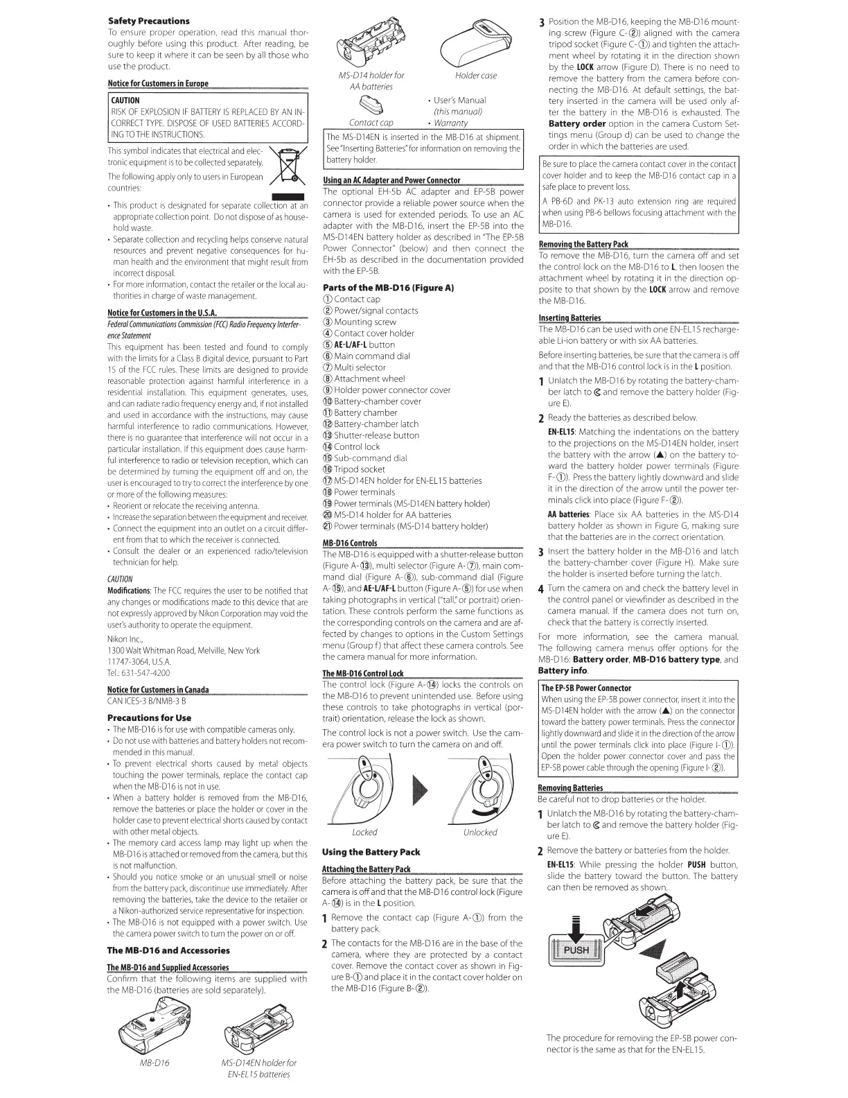
MB-016
MS-0
14EN
holder
for
EN-EL
15
batteries
MS
-0 14 holder for
Mbatteries
Holder
case
•
User's
Manual
(this
manual)
Contact
cap
• Warranty
The
MS-D14EN
is
inserted
in
the
MB
-D16
at
s
hi
pment.
See
"Inserting
Batteries"
for
information
on
removing
the
battery
holder.
Using
an
AC
Adapter
and
Power
Connector
The
optional
EH
-
5b
AC
adapter
and
EP-5B
power
connector provide a
reliable
power
source
when the
came
ra
is
used
for extended periods.
To
use
an
AC
adapter with the
MB-
0
16,
insert the
EP-58
into the
MS-D14EN
battery holder
as
described
in
"The
EP-5B
Powe
r
Co
nnector" (below)
and
then connect the
EH-5b
as
described in the documentation provided
with the
EP-58
.
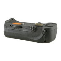
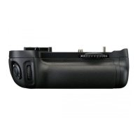
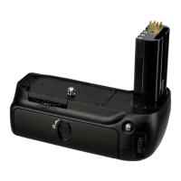
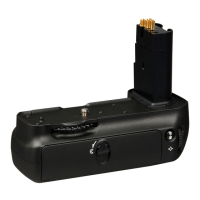
Parts
of
the
MB-016
(Figure
A)
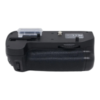
CD
Contact
cap
®Power/signal contacts
@Mounting
screw
®Contact
cover
holder
@
AE-l/AF
-L button
®
Main
command dial
(])
Multi selector
® Attachment wheel
®Holder
power connector cover
® Battery-chamber
cover
([j)
Battery chamber
@ Battery-chamber latch
@ Shutter-release button
@ Control lock
@
Sub
-command dial
® Tripod
socket
@
MS-014EN
holder
for
EN-EL
15 batteries
®
Power
terminals
@
Powerterminals
(MS
-
D14EN
battery
holder)
® MS-0
14
holder
for
AA
batter
ies
I@
Power
terminals
(MS-D14
battery holder)
MB-016
Cont
r
ols
The
MB-016
is
equipped with a
shutter-release
button
(Fig
u
re
A-
@
),
multi selector
(Figure
A-(])), main com-
mand dial
(Figure
A-@), sub-command d
ial
(Figure
A
-@
),
and
AE-l/AH button
(Figure
A-@)
for
use
when
taking photographs
in
ver
t
ical
("tall;'
or
portrait) orien-
tation.
These
controls perform the
same
functions
as
the corresponding controls
on
t
he
camera
and
are
af-
fected
by
changes
to
options
in
the
Custom
Settings
menu
(Group
f) that affect
these
camera
controls.
See
the
camera
manual
for
more information.
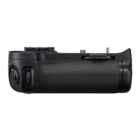
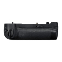
The
MB·D16
Cont
r
ol
Lock
T
he
control l
ock
(Figure
A-
@) l
ocks
the contr
ols
on
the MB-016 to prevent unintended
use
.
Before
using
these
controls
to
take
photographs
in
vertical (por-
trait) orientation,
release
the
lock
as
shown.
The
control lock
is
n
ot
a power switch.
Use
the
cam-
era
power switch to turn the
camera
on
and
off
.
Locked
Unlocked
Using
the
Battery Pack
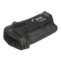
Attaching
the
BatterY.
':"
P
.::
a
~
ck
~--....,.-:----:---:
Before
attaching the battery
pack,
be
su
re
that the
ca
mera
is
o
ff
and
that the MB-016 control lock
(Figure
A-
@)
is
in
the L position.
1
Remove
the contact
cap
(Figure
A-CD)
from the
battery
pack.
2
The
contacts
for
the
MB-D16
are
in
the
base
of
the
camera,
where they
are
protected
by
a contact
cover.
Remove
the contact
cover
as
shown
in
Fig-
ure
B-CD
a
nd
pl
ace
it
in
the contact
cover
holder
on
the MB-016
(Figure
B-@).
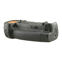
3
Position
the
MB-D16,
keeping the MB-016 mount-
ing
screw
(Figure
C-®l
alig
n
ed
with the
camera
tripod
socket
(Figure
C-CDJ
and
tighten the attach-
ment wheel by rotating it
in
the direction shown
by
the
LOCK
arrow
(Figure
D).
There
is
no
need
to
remove the battery from the
camera
before con-
necting the
MB-D16.
At
default
settings,
the
bat
-
tery inserted
in
the
camera
will
be
used
only
af-
ter the battery in the MB-016
is
exhausted.
The
Battery order option
in
the
camera
Custom
Set-
tings menu
(Group
d)
can
be
used
to change the
order
in
which the
ba
tt
eries
are
used.
Be
sure
to
place
the
camera
con
t
act
cover
in
the
contact
cover
ho
ld
er
and
to
keep
the
MB
-D
16
contact
cap
rn a
safe
place
to
prevent
loss.
A
PB
-
6D
and
PK-13
auto
extension
ring
are
r
equired
when
using
PB-6
bellows
f
ocusing
attachmen
t wi
th
the
MB-D16.
Removing
the
Batte!Y.
t.
P
~
a
~
ck
!)....
_-:-----,-....,.
To
remove the
MB-D16,
tu
rn
the
camera
off
and
set
the control lock
on
the
MB
-016
to
L, then
loosen
the
attach
men
t wheel
by
rotating it
in
the direction op-
posite to that shown by the
LOCK
arrow
and
remove
the
MB
-016.
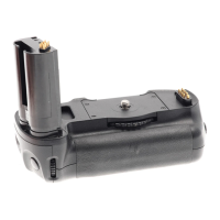
Inserting
Batteries
The
MB-D16
can
be
used
with
one
EN-EL
15
recharge-
able
Li-ion
battery
or
with
six
AA
batteri
es.
Before
inserting
batteries,
be
sure
that the
camera
is
off
and
that the MB-016 control
lock
is
in
t
he
L position.
Unlatch the
MB-016
by
rotating t
he
battery-cham-
ber latch
to
€
and
re
move the battery holder
(Fig-
ure
E).
2 R
eady
the batteries
as
described below.
EN·EL15
: Matching the indentati
ons
on
the battery
to the projections
on
the
MS
-
014EN
holder,
inse
rt
t
he
battery
wi
th the arrow (A )
on
the battery to-
ward
the battery holder power terminals
(Figure
F-CDJ.
Press
the battery lightly downward
and
sl
i
de
it
in
the direction
of
the arrow until the power ter-
minals click into
place
(Figure
F-@).
AA
batteries
: Pl
ace
six
AA
batteries
in
t
he
MS-014
ba
tt
ery
holder
as
shown
in
Figure
G,
mak
i
ng
sure
that the batteries
are
in
the correct
or
ientati
on.
3 Insert the battery holder
in
the MB-016
and
l
atch
the battery-chamber
cover
(Figure
H).
Make
sure
the holder
is
inserted before turning the
latch.
4
Turn
the
camera
on
and
check
the battery l
evel
in
the control
pane
l
or
viewfinder
as
descr
i
bed
in
the
camera
manual.
If the
camera
does
not turn
on,
check that the battery
is
correctly inserted.
For
more information,
see
the
camera
manual.
The
following
camera
menus
offer options
for
the
MB-D16:
Battery order,
MB
-
016
battery type,
and
Battery info.
The
EP-SB
Power
Connector
When
using
the
EP
-
58
power
connector,
insert
it
i
nto
the
MS
-
D14EN
holder
with
the
ar
r
ow
(A )
on
the
connector
toward
the
battery
power
term
i
nals.
Press
the
connector
lightly
downward
and
slide
it
in
the
direction
of
the
arrow
until
the
power
terminals
click
into
place
(Figure
1-
CDJ
.
Open
the
holder
power
connector
cover
and
pass
the
EP-5B
power
cable
thro
u
gh
the
opening
(Figure
1-
®l.
Remo
v
ing
Batter
i
es
Be
ca
reful not to drop batteries
or
the hol
der.
Unlatch the MB-016
by
rotating the battery-cham-
ber latch
to
€
and
remove the battery holder
(Fig-
ure
E).
2
Remove
the battery or batteries from the holder.
EN
·
EL15
: While
pressing
the holder
PUSH
button,
slide
the battery toward the button.
The
battery
can
then
be
removed
as
shown.
The
procedure
for
removing the
EP
-
58
power con-
nector
is
the
same
as
that for the
EN-EL
15.
 Loading...