EM-32
< REMOVAL AND INSTALLATION >
[VQ40DE]
EXHAUST MANIFOLD AND THREE WAY CATALYST
• Check the surface distortion of the exhaust manifold mating sur-
face with straightedge and feeler gauge.
• If it exceeds the limit, replace exhaust manifold.
INSTALLATION (LH)
Installation is in the reverse order of removal.
Exhaust Manifold Gasket
Install the exhaust manifold gasket in direction as shown.
• : Front
• A: Identification hole
Exhaust Manifold
• If exhaust manifold studs were removed, install them and tighten to specification.
• Install exhaust manifold and tighten nuts in numerical order as
shown.
CAUTION:
Use new exhaust manifold nuts for installation.
NOTE:
Tighten nuts No. 1 and 2 in two steps. The numerical order No. 7
and 8 show second step.
- : Front
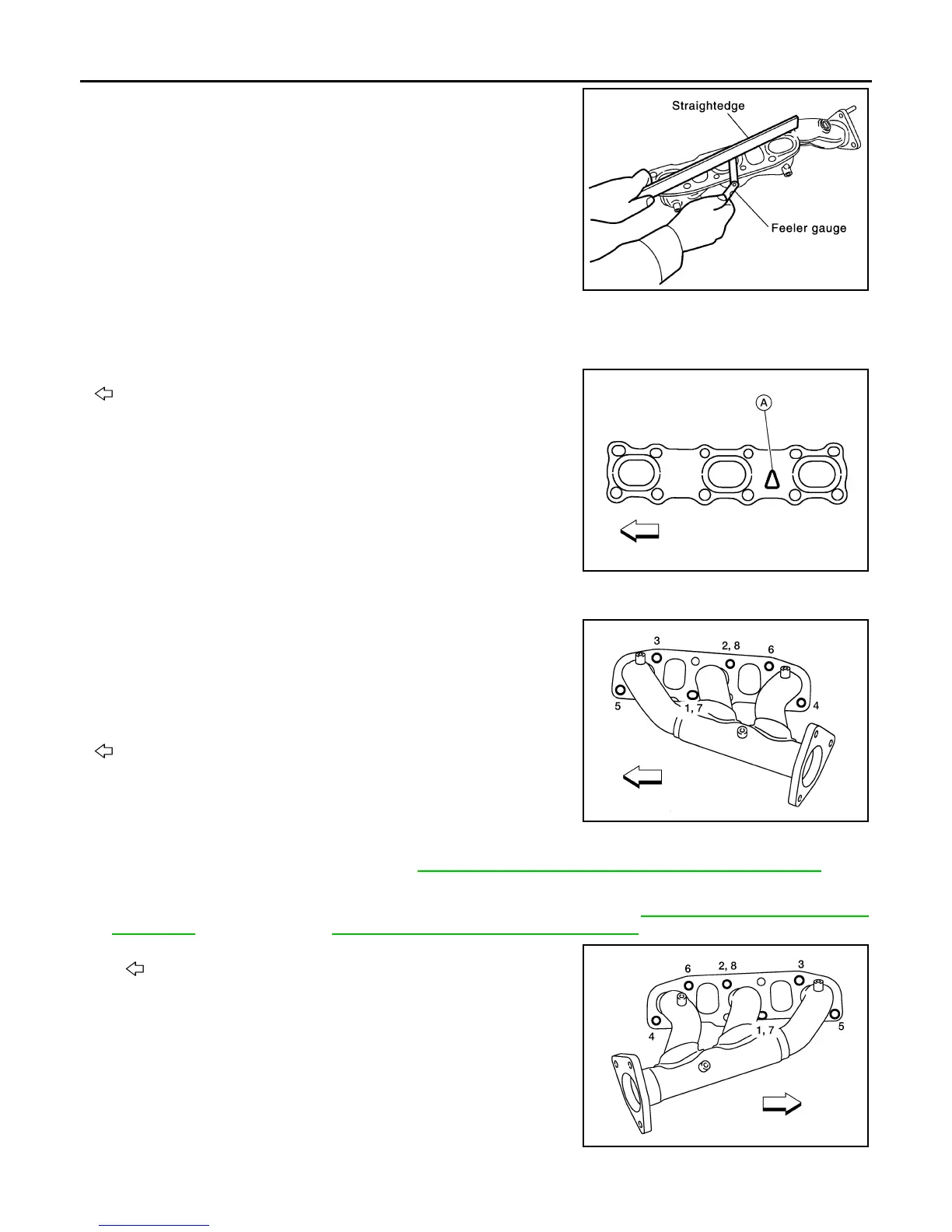
REMOVAL (RH)
1. Remove three way catalyst (RH). Refer to EM-30, "Removal and Installation (Three Way Catalyst)".
2. Remove heat shield from lower dash panel.
3. Remove support bolts from A/T fluid charging pipe (A/T models). Refer to TM-248, "Removal and Installa-
tion (2WD)" (2WD models), or TM-250, "Removal and Installation (4WD)" (4WD models).
4. Loosen nuts in reverse order as shown.
• : Front
NOTE:
Disregard the numerical order No. 7 and 8 in removal.
5. Remove exhaust manifold (RH) and exhaust manifold cover (RH) together.
Limit : 0.3 mm (0.012 in)
PBIC1096E
AWBIA0726ZZ
AWBIA0725ZZ
AWBIA0727ZZ
Revision: January 2013 2013 Xterra