CAMSHAFT
EM-79
< REMOVAL AND INSTALLATION >
[VQ40DE]
C
D
E
F
G
H
I
J
K
L
M
A
EM
N
P
O
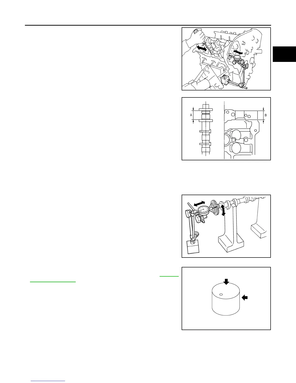
• Install dial indicator in thrust direction on front end of camshaft.
Measure the end play of dial indicator when camshaft is moved for-
ward/backward (in direction to axis).
• Measure the following parts if out of the limit.
- Dimension (A” for camshaft No. 1 journal
- Dimension “B” for cylinder head No. 1 journal bearing
• Following the standards above, replace camshaft and/or cylinder
head.
Camshaft Sprocket Runout
1. Put V-block on precise flat table, and support No. 2 and 4 journal of camshaft.
CAUTION:
Do not support journal No. 1 (on the side of camshaft sprocket) because it has a different diameter
from the other three locations.
2. Measure the camshaft sprocket runout with dial indicator. (Total
indicator reading)
• If it exceeds the limit, replace camshaft sprocket.
Valve Lifter
Check if surface of valve lifter has any wear or cracks.
• If anything above is found, replace valve lifter. Refer to EM-129,
"Standard and Limit".
Valve Lifter Clearance
VALVE LIFTER OUTER DIAMETER
Standard : 0.115 - 0.188 mm (0.0045 - 0.0074 in)
Limit : 0.24 mm (0.0094 in)
SEM864E
Standard : 27.500 - 27.548 mm (1.0827 - 1.0846 in)
Standard : 27.360 - 27.385 mm (1.0772 - 1.0781 in)
KBIA2404J
Limit : 0.15 mm (0.0059 in)
PBIC0930E
KBIA0182E
Revision: January 2013 2013 Xterra