EM-96
< REMOVAL AND INSTALLATION >
[VQ40DE]
CYLINDER HEAD
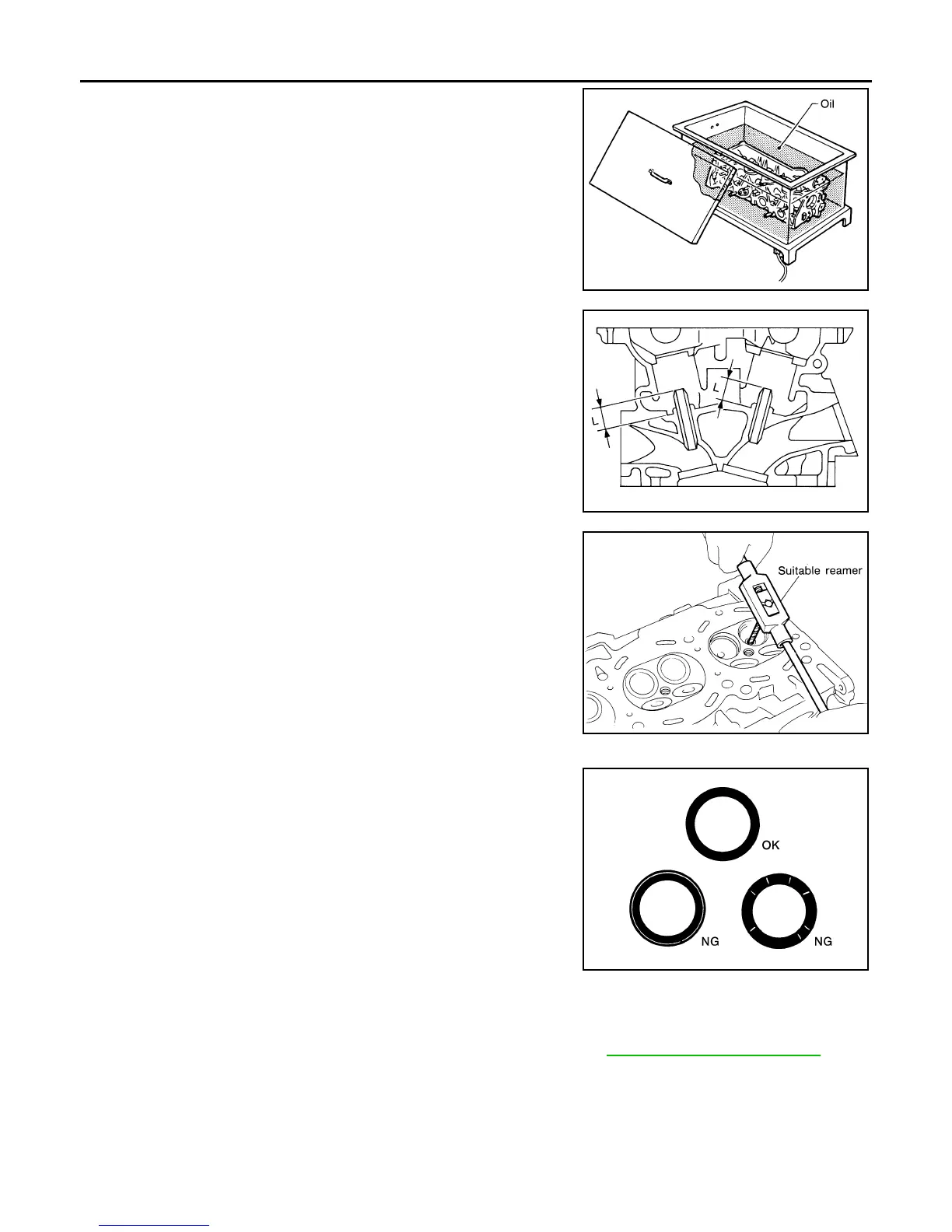
4. Heat cylinder head to 110° to 130°C (230° to 266°F) by soaking
in heated oil.
5. Press valve guide from camshaft side to the dimensions as
shown using suitable tool.
WARNING:
Cylinder head contains heat. When working, wear protec-
tive equipment to avoid getting burned.
6. Apply reamer finish to valve guide using suitable tool.
VALVE SEAT CONTACT
• After confirming that the dimensions of valve guides and valves are
within the specifications, perform this procedure.
• Apply prussian blue (or white lead) onto contacting surface of valve
seat to check the condition of the valve contact on the surface.
• Check if the contact area band is continuous all around the circum-
ference.
• If not, grind to adjust valve fitting and check again. If the contacting
surface still has “NG” conditions even after the re-check, replace
valve seat.
VALVE SEAT REPLACEMENT
When valve seat is removed, replace with oversized [0.5 mm (0.020 in)] valve seat.
1. Bore out old seat until it collapses. Boring should not continue beyond the bottom face of the seat recess
in cylinder head. Set the machine depth stop to ensure this. Refer to EM-129, "Standard and Limit"
.
CAUTION:
Do not scratch cylinder head by excessive boring.
SEM008A
Projection “L”
Intake and exhaust
: 12.6 - 12.8 mm (0.496 - 0.504 in)
SEM950E
Standard:
Intake and exhaust
: 6.000 - 6.018 mm (0.2362 - 0.2369 in)
SEM932C
SBIA0322E
Revision: January 2013 2013 Xterra