SYSTEM
STC-7
< SYSTEM DESCRIPTION >
C
D
E
F
H
I
J
K
L
M
A
B
STC
N
O
P
SYSTEM
EPS SYSTEM
EPS SYSTEM : System Description INFOID:0000000007207864
• EPS control unit performs an arithmetical operation on data, such as steering wheel turning force (sensor
signal) from the torque sensor, vehicle speed signal, etc. Then it generates an optimum assist torque signal
to the EPS motor according to the driving condition.
• In case of an error in the electrical system, the fail-safe function stops output signals to the EPS motor. Refer
to STC-8, "EPS SYSTEM : Fail-Safe"
.
• EPS control unit decreases the output signal to EPS motor while extremely using the power steering func-
tion (e.g., full steering) consecutively for protecting EPS motor and EPS control unit (Overload protection
control). Refer to STC-8, "EPS SYSTEM : Protection Function"
.
• Extensive steering at low speed will cause the ECU and MOTOR to heat up, once temperature reaches crit-
ical point ECU will reduce current to reduce heat up. System will recover as temperature lowers (reduced or
no assistance).
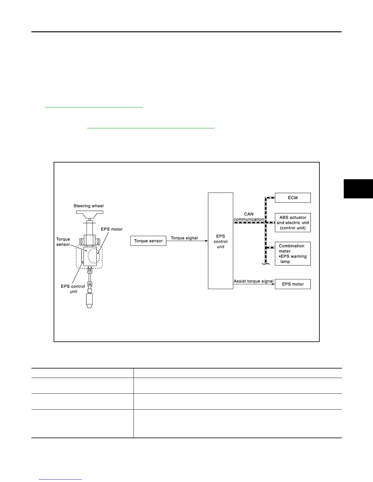
SYSTEM DIAGRAM
INPUT/OUTPUT SIGNAL
Communicates the signal from each control unit via CAN communication.
EPS WARNING LAMP INDICATION
• Turn ON when there is a malfunction in EPS system. If indicates that fail-safe mode is engaged and enters a
manual steering state (Control turning force steering wheel becomes heavy).
JPGIB0005GB
Control unit Signal status
ECM
• Transmits mainly the following signals to EPS control unit via CAN communication.
- Engine status signal
ABS actuator and electric unit (control unit)
• Transmits mainly the following signals to EPS control unit via CAN communication.
- Vehicle speed signal (ABS)
Combination meter
• Transmits mainly the following signals to EPS control unit via CAN communication.
- Vehicle speed signal (METER)
• Receives mainly the following signals from EPS control unit via CAN communication.
- EPS warning lamp signal
Revision: March 2013 2012 Versa Sedan