Technlcal Parameters (Model AIBICIL)
M
Range
-
pitivity ~ccurac;~T
I
eoresenlatian
alculated as a
DCV
50v1500v11000v
-
--
PP
ercentage of
2
5% indicated value
5%
a
The capacitor shauld be completely discharged befue each measurement atherwise the
measurement
error wlll increase
b Palarized capacitors should be connected according to the correct polarity othenvise the measurerent
error
and loss reeietance
will
ncrease
kapacitance C(1F)
1~x1 ~110
Mearurtng Range(pF)
~VF
1OpF bp!-10ov~ ~~~.$OOpF
1
ACV
Resistance
fi
BATT
Buuer
LV detectton
LED detection
hFE
lnfrared
remoter
etect
on
Standard
reslsiance box
LIVE wire
detect~on
i
Frequency messurement (Hz) (N model only)
I) Insert the black test lead into the "COM jack. and the red test lead into the 'VOmA lack.
2) Set the gear rotary switch to the
"Hz"
range. and connect the test pen 10 the lrequency source
lVPP>lVI.
I
ovi~ovi~5öv1~oo~iooov1~~oöv
R-IIRrlOl R*IOOiRxlkl~xl~k/~~~k
1
rp
~.lk20
-
-1
1 2Vi1 5Vi2Vi3V13 6V
~=sn-l2n(oni~ models ABIC)
The burrer wolks when 11
1s
lawer thah 300
Rxl
xl
k
RxlOk IKV
Voltage regulation tube within 10V delection current DC 5mA (oniy Model L)
0-1000hFE 1~x10
vertical angletl5 Red Iight emitting tiibe indication (Iight up) (only BiCIL models)
distancel-30cm
0 02510 5i5/501500/5k/20ki50ki200ki1hi2 25Ml4 5Ml9Mi22 5M
Red Iight emining tube ind cation (ligh(up 220V AC detection) (only model
B
)
Frequency
Hz
Measurlng Range 1 1110000 'O1tOÖÖ
1
In~trUft,on~
Before
use
check whether the pointer polnts to the mechanical
Zero
pasition if it does not point 10 the
Zero pasition you can turn the "pointer 10
Zero'
an the wver Make the painter point 10
zera
DC voltage measurement (DCV)
1)
Insert the black test lead in10 the 'C0M"lack and the red lest lead tnto the VnmA'lack
When measunng a voltage greater than lOOOV insen
he
red test pen mto the 2500Vlack and sei the
'gear
rotaiy swtch' to 1000V
2) Set the gear rotary swtch 10 the 'DCV' range and wnnect the test pen to the load or signal source
under test
Transistor
hFE Parameter measurement
I) Set the gear rntary switch to "hFE" (resistance
x
10
gears).
2) First determine whether the Iransirtor
is
PNP
or
NPN. and then inseri the three pins E, B, and C of the
tested tube into Ihe corresponding test sockets
on
the Panel, and the vaiue indicated by the pointer
deflection
is the value of the transistor's DC ampliflcatian factor hFE.
Notice'
If the pointer deflectian indeation
is
greater than 1000. first check whether the pins are insened
inconectly and whelher the transistor
is
damaged.
Diode measurement
(*)
(N model only) (Maximum voltage 3V)
I) Insert the black test lead into the "COM jack, and the red lest lead inlo the "V0mA' jack (the polanty of
the black lest lead is "+').
2
5ct ine
yedr
rolary s~iicn 10 tne
'*.
range. an0
he
volnier
H
I
nefiecl oirect
y
to the ngnl hll-scae
00%
i
i
n
at t~i
s
:imc
H"
cn
s
a
norma pnenomenon. Connect tne test
pen
to tne
o
ode
~nder lest Ine
loruar, cona.clion Dointcr na cnli
Ilie conaJct
on
rdlage ard Ine orainaiy .€D l.gn:.em tling d oae
s
I
t at tne Same t me
wen
ridicacing
:ne
B
ward
.oliaye
LEDl Voltage regulator tube measurement (L modd anly) (Iight-emitting tubes within 10V can be
measured)
Pul the gear position rotary switch
tn
the
"*"
pas6tiOn, and the pointer will devlate 10 the right
near
the
fuli scale. This
is
a
normal phenomenon and
can
be measured direclly. When measuring. the red test
pen
IS
the output voltage
"+'.
aod the faward measurement indicates the fofward valtage dmp af the PN
lunction
of
the diode. It
can
also measure
various
type6 of LED Iightemining dodes. and Iight up the
Iight-emttting tube while indicating the foward voltage drap The
reverse
measurement
is
the steady
vollage value of the
Zener
lube (the
Zener
tube is reversed). please refer to the special scale far the
""
Zener lube far the reading.
Buuer continuity test
(*)ji
)
1) Insert the black test lead mto the "COM" lack, and the red test lead tnfo the "VfimA iack.
2) Set the gear rotary switch to the
"'))j'
range, and Oannect the lest pens to bath ends of the circuit ta
be checked.
3)
If the resistance value befween the wo points to
te,
checked is less than 300 (AIBICIL type)
or
150 (N
type). the buner will beep immediately.
Note The orcuil under test must be checked for contiiuity when the power is cut
off,
because any load
srgnal will make the burzer sound. resulting
in
wrong jpdgment.
lnfrared remote control emission signal detection
(E)
This is set for ludging whether the infrared remate control transminer
is
wolking normally When adlusting
10 thls pos1110n. allgn the transminer head of the infrar6d remote wntrol transmcner vertically with the
infrared receiver, the deviatlon should not be greater than t15'. and press the remote wntml launch
button. If the red light-emining tube an the right
is
flashtng at the Same time, 11 means that the transminer
Notice:
a.
If you da not know the measured voltage range before measurement. you should set the gear rotaiy
sw~tch lo ihe highest range end lawer it step by step.
b.
If the pointer exceeds the maximum scale of the dal. lt means that the measured voltage has exceeded
the range, and the gear rotaiy switch needs to be adlusted lo last gear
c.
Pay special attention to avoid electric shock when measuring high voltage.
AC voltage measurement (ACV)
I) Insert the black test lead into the "COM jack, and the red lest lead in10 the 'V0mA" lack.
When measuring
a
voltage greater than 1000V. Insert the red test pen into the 2500Vjack. and set the
"gear rotary switch' 10 1000V.
2) Set the gear rolary switch lo the "ACV' range. and connect the lest pen to the load or signal source
under test.
Note: See
DC voltage measurement notes
a.
b,
C.
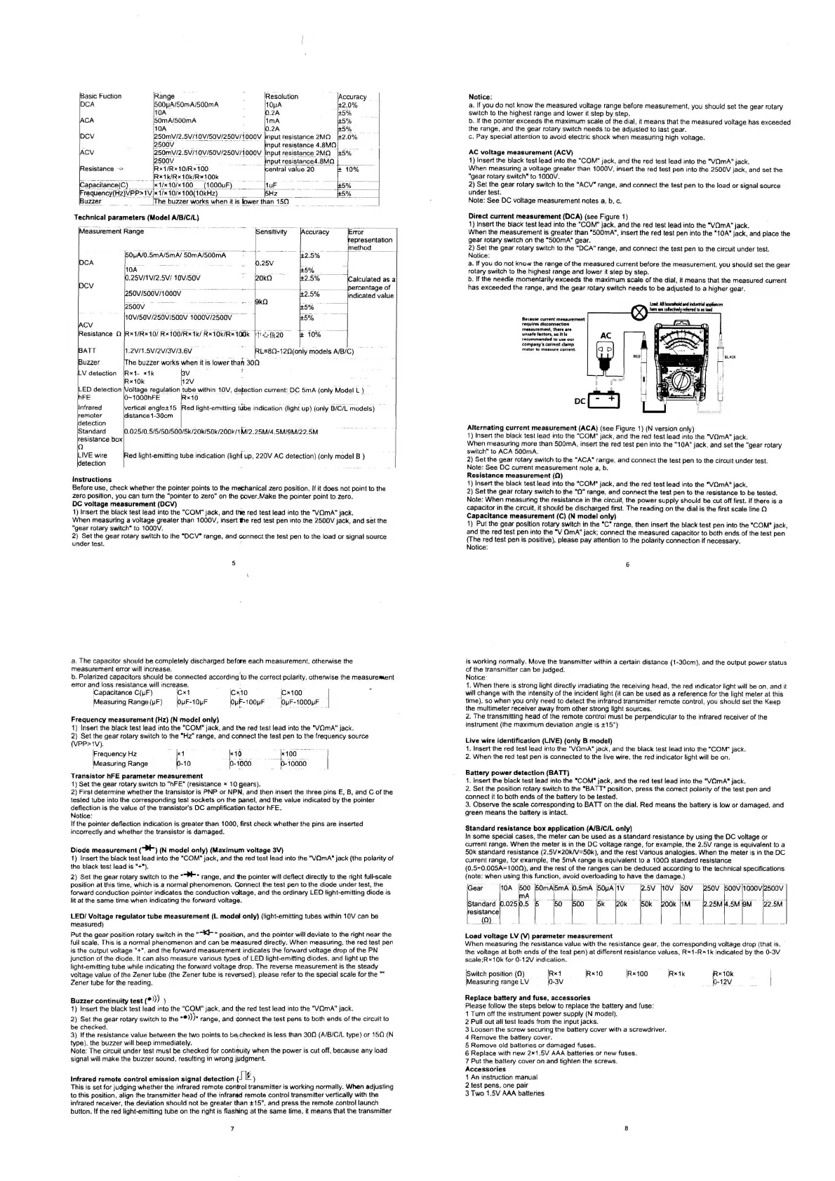
Direct eurrent measumment (DCA)
(see
Figure 1)
I) lnsen the black test lead into the "COM iack. and the red test lead into the 'V0mA"lack.
When the measurement is greater than '500mA'. Insert the red lest
pen
into the 'IOA' jack, and place the
gear rotary swtch
on
the 'SOOmA" gear.
2) Set the gear rotary swltch 10 the "DCA' range, and wnnect the test pen 10 the circuit under test.
Natice
a. lf yav do not knou the range of the measured current before the measurement. you should set the gear
rotary swtch
to the highest range and lower it step by step.
b.
If the needle momentartly exceeds the maximum scale ofthe dial, it means that the measured current
has exceeded the range, and the gear rotary swtch needs to be adjusted to a higher gear.
LotU~nd~~.
ha..nnnni,~i"W
Alternating current measurement (ACA)
(See
Figure 1) (N version only)
1) Inserl the black tesl lead into the "COM lack, and the red test lead in10 the 'VnmA'lack.
When measunng more than 50OmA. Insert the red test pen cnto the "10A lack, and set the "gear rataiy
switch' to ACA 500mA.
2) Set the gear rotary switch 10 the '"ACA' range. and connect the test pen to the circut under test.
Note See DC current measurement note a. b.
Resistance measurement
(0)
1
insen
lhe
oiac-
'es1 .eaa
into
tne "COM'
au
ano Ihe rea lest eao iila lhe 'VnmPI' acr
2 Set Ine gear rotary s* Ich 10
me
'U
range an0 wnnecl lne lest pen 10 tne res slanie to be leslea
hole Wnen meas-nng In< resislance
.n
the rirc.it Ine DoHer s.pp
y
rrio..
<I
be
cul
oii
f rsi. if rnere s
a
capacltor
n
tbe
C
rcJ1. 1 Sn0 . d be a schargea first. The read
ng
ori the atai
5
the trsl sca
e
ne
n
Capacltance mcasurcment (C) (N madcl onlyl
1 P-i tnc gear posit On rolaiy
sw
Ich
In
Ine 'C' ranqe lhen
nserf
fnc biack lest pen nto tne 'COM' iacr
and tne red test
Den
nto me
1
OmA'
.ac%
conneci tiie measLrea capacilor 10 ootn ends of tne rest ven
(rne rea lest pen is pos t
ue
D.easc pay anenl
on
to tne no
ar
ry
connect on
d
necessdry
is
warking nomally. Mave the transmltler wlthm
a
certain distance (1-3Ocm). and the output power status
oi the transminer
can
be ludged
Notice
1. When
there
s
strong Iight directly irradiating the recevtng head. the red indicator Iight will be
on,
and it
wlll change wth the intensity of the incident Iight (it
can
be used as a reference farthe Iight meter
at
this
time).
so
when
you only need to detect the infrared transminer remote contral, you should Set the Keep
the multimeter receiver away from other strong light sources
2. The transmitting head of the remote control must be perpendicularto the infrared receiver of the
instrument (the maximum devlation angle is t15')
Live wire identification (LIVE) (only B model)
1.
Insert the red test lead into the "VfimA']ack, and the black feit lead into the 'COM' jack
2.
When the red test pen
is
connected to the live wre. the red indicator Iight will be
on.
Banew
power
detection (BATi1
1
insen
Ine back lest leaa niu lne 'COM' tack and the rea teil leao inio ine 'VnrnA'
acd
2
Set Ine 00s Ion rotaiy s~tcn to ine 'BA
I
T' paiit
on
Drcw
tne caneci polar iv
o'
ine tesi
pcn
dno
connect it to both ends of the balleiy 10 be tested.
3. ObSeNe the scale cnrresponding 10 BATT on the dial. Red means the battery
is
low
or
damaged, and
green means the banery
1s
intact.
Standard resistance bar application (AIBICIL only)
In
some special
cases,
the meter
can
be used
as
a
Standard resistance by usmg the DC vokage or
current range. When the meter is in the DC voltage range. for example. the 2.5V range
is
equivalenl to
a
50k standard resistance (2.5Vr20kN=50k). and the rest Vanous analogles. When the meter
s
in
the DC
cunent range,
hr
example. the 5mA range
is
equivalent 10 a 1000 Standard reslstance
(0.5-0.005A=lOO~), and the rest of the ranges
can
be deduced according to the technlcal spec8fications
(note. when using this function, avaid overioading 10 have the damage.)
l~ear IIOA
~OO
bom~bmÄ D.5mA ~O~A~IV 127% li0FbÖ~Dso~ 1sOov~50ivl
Load voltage LV
(W
Parameter mcasurement
h
nun
mcas-nng inc
rci
stdrice va
-L
n
In ine res slaiicc qear tne CorrLspona
ny
ro tage crop ;nai
9
:he <aiistqr
AI
~0th
e
n~9
01 tne 16
SI
perl
ai
a Ife rcnl resislancc .al-sr H-1-R- Ir
nu
~nicd
U,
tnr 0-1\
scaie,RxlOk for 0-l2V indcation
sw~tch pos~tqon (0)
RXIO
~RXIOO
RXI~
Measuring range LV
Replacc bancry and fuse. accessories
Pease
1 OI ini sleos oelo* 10 rppace lhe oallery ana f.se
1
'.rn
<Y
tnr nilrdnenl poner ~-pply
,h
moa"
i
2
P.. l0.d
d
1
teil 13a8$ f~im
1"''
nOL1
aC65
7.
3 Loosen the screw
securina
the banervcoverwith
a
screwdriver
4 Remove the banery
Cover.
5 Remove old balteries ar damaged fuses.
6
Replace with new 2x1.5V AAA batteries
or
new fuses
7
Pul the battery
caver
on
and tighten Ihe screws.
Acceoiorier
1 An instruction manual
2 fest pens,
one
pair
3 Two 1.5V AAA batteries
 Loading...