5
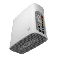
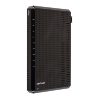
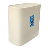
Replace the ONT with a new unit. For details, Chapter 4, “Install or replace a BGW320-505
indoor ONT”
.
6
Connect the Ethernet cables to the ONT and GE ports; see Figure 4-2, “BGW320-505 ONT
connections” (p. 40)
for the location of these ports.
7
Connect a telephone to the RJ-14 POTS port.
Contact your service provider for details, especially if you have an alarm system.
8
DANGER
Hazard
Fiber cables transmit invisible laser light. To avoid eye damage or blindness, never look directly
into fibers, connectors, or adapters.
WARNING
Equipment Damage
Be careful to maintain a bend radius of no less than 1.5 in. (3.8 cm) when connecting the fiber
optic cable. Too small of a bend radius in the cable can result in damage to the optic fiber.
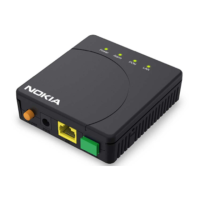
Connect the fiber optic cable with the SFP adapter into the SFP connector.
Figure 4-2,
“BGW320-505 ONT connections” (p. 40)
shows the location of the fiber optic connector.
9
Install the power supply according to manufacturer specifications.
Note: Observe the following:
• Units must be powered by a Listed or CE approved and marked limited power source
power supply with a minimum output rate of 12VDC, 4A.
10
Power up the unit by connecting the power cable; see Figure 4-2, “BGW320-505 ONT
connections” (p. 40)
for the location of the power input.
11
If applicable, press the WPS button to enable the WPS discovery mode on new WiFi devices.
Install or replace a BGW320-505 indoor ONT
Replace a BGW320-505 indoor ONT
BGW320-505
June 2022
Issue 3 41
© 2022 Nokia. Nokia Confidential Information
Use subject to agreed restrictions on disclosure and use.
3FE-47753-AAAA-TCZZA
 Loading...
