www.norcold.com/cda
13
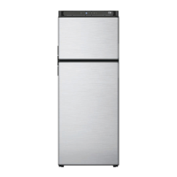
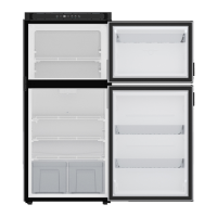
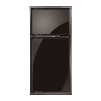
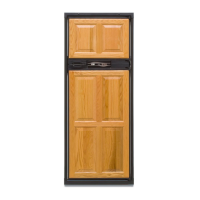
N611v, N811v ModelsRefrigerator Service Manual
Prior to performing the diagnostic steps called out in the
following pages; fi rst verify these four important diagnostic pre-
checks. In most cases doing so, in and of itself, will remedy the
problem at hand.
1. The refrigerator is plugged into a known working AC
outlet with a voltage between 108VAC and 132VAC
2. Extension cords are not being used to supply AC power
to the refrigerator
3. The refrigerator is connected to a known working DC
power supply and/or battery supplying between 10.5
and 15.4VDC
4. LP gas is available to the refrigerator and is regulated
between 10.5 and 11.5”WC (Inches of Water Column)
Diagnostic Prechecks
The N611v, N811v model refrigerators have the ability to
recognize various fault conditions and will display a unique
error/fault code accordingly.
Should none of the heat source inputs be available, the power
ON indicator light will be ON continuously and will be red in
color.
Fault Codes - cont’d.
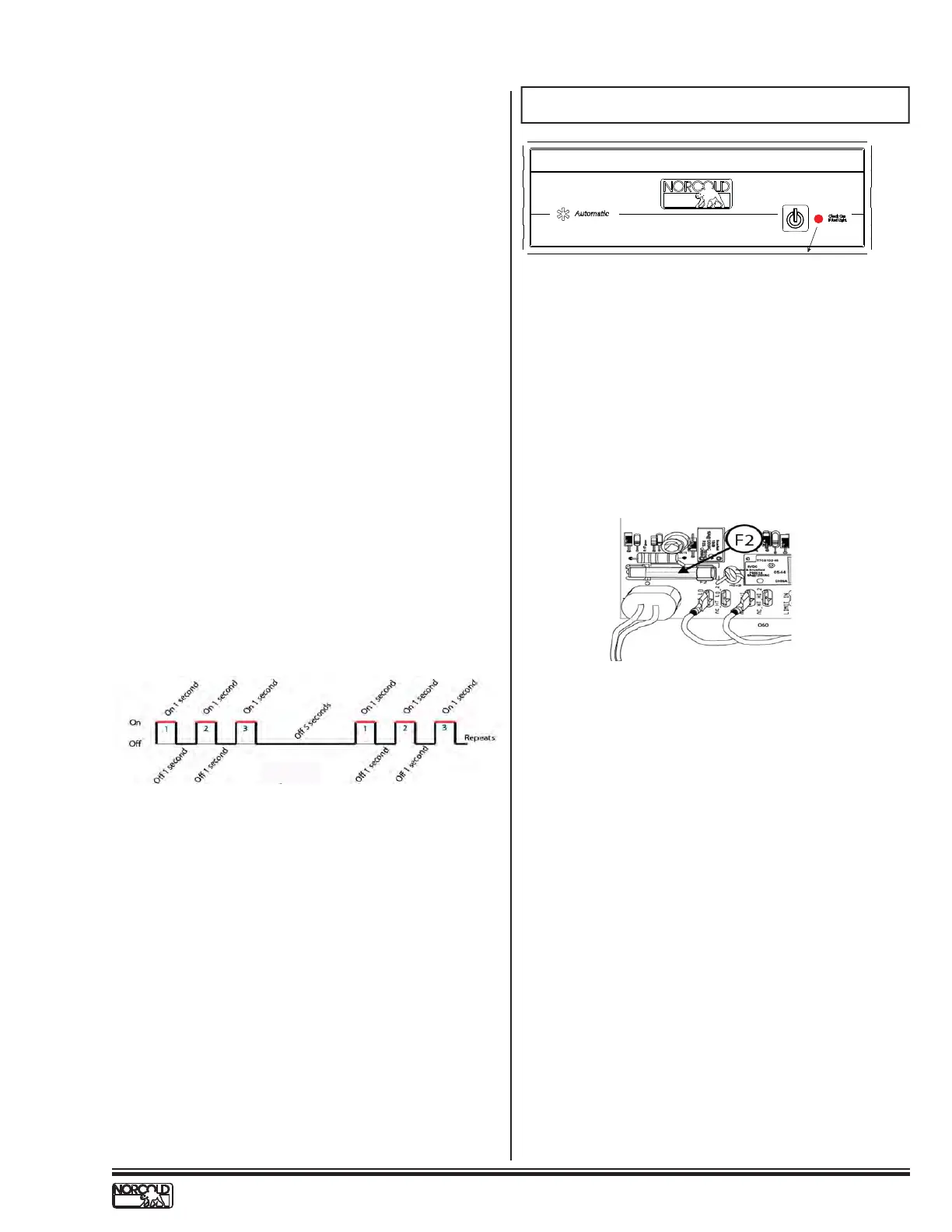
ALL other fault codes will be displayed using fl ash patterns.
The term “fl ash pattern” means the power ON indicator light is
turned ON and OFF to create a numeric pattern. These fl ash
patterns directly correspond to particular fault codes. That is to
say, for example, fault code 3 will be indicated by fl ashing the
power ON indicator light RED 3-times, followed by a 5-second
pause, and then repeated as long as the fault condition is
present. See Fig. 4 below.
NOR000123A
Fig. 4 - Flash Patterns
Fault Code Flash Patterns
■ Because the AC voltage was sensed to be out of tolerance,
the refrigerator defaulted to LP gas mode. While in Auto LP
gas mode, either a flame was not established or a flame
was not sensed-a gas lockout condition now exists (solid
red light).
Verify:
■ All LP gas shutoff valves (including manual shutoff
on gas valve itself) are open
■ LP Gas pressure at refrigerator is 11.5” W.C. (water
column)
■ LP gas supply line is free of air
■ Burner is clean
■ Electrode-to-burner air gap is between 1/8” and
3/16”
■ Spark-sense igniter wire is installed correctly and in
good operating condition / continuity
■ Gas valve solenoid is in good operating condition
(Coil resistance ≈74Ω to 92Ω)
■ Wires to the gas valve are connected and in good
operating condition / continuity
■ Power Board supplies 12VDC to gas valve when
required
Solid Red Indicator Light
NOR000127-0A
CODE 0
CONSTANT RED INDICATOR LIGHT
The following conditions will cause the power ON indicator to
be solid RED:
■ The AC input voltage to the refrigerator was sensed to be
less than 85VAC.
Verify:
■ The refrigerator is plugged into a known working
AC outlet supplying a minimum of 85VAC
■ The AC power cord is in good operating condition
■ The glass 8-amp fuse (F2) on the Power Board is
intact.
 Loading...