www.norcold.com/cda
19
N611v, N811v ModelsRefrigerator Service Manual
Components
When working on the refrigerator LP gas system:
• Do not alter or modify the burner tube anti-vibration
loop.
• Do not cross thread fi ttings. Exercise extreme care
when connecting and disconnecting propane gas
components.
• Leak test all of the refrigerator propane gas system
fi ttings after servicing, replacing, or repairing any LP gas
system component.
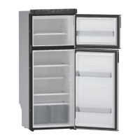
Solenoid Gas Valves
The manual shut-off valve and the pressure tap are integrated
into the solenoid gas valve. To manually shut-off gas to the
burner, rotate the knurled shut-off knob one-quarter turn (90
degrees) clockwise until the screw slot on the face of the knob
is vertical or perpendicular to the fl ow of gas. Refer to Fig. 9
below.
Solenoid Gas Valve Connections
The solenoid gas valve inlet fi tting is 3/8 inch, male threads;
the outlet fi tting is 1/4 inch, male threads.
Fig. 9 - Solenoid Gas Valve.
LP Gas System - cont’d
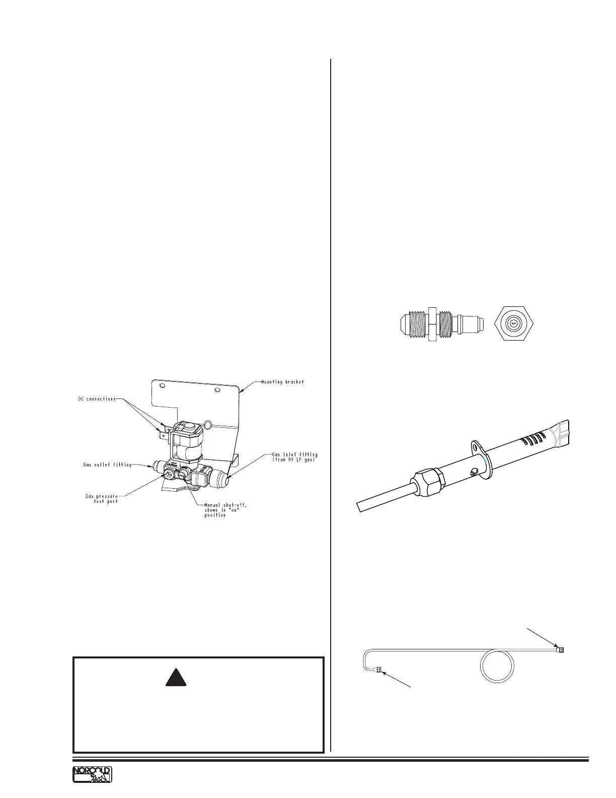
Orifi ce
The orifi ce controls the fl ow of propane gas to the burner.
When replacing the orifi ce always use the size orifi ce specifi ed.
Using the wrong size or a damaged orifi ce will alter the amount
of propane fl owing to the burner.
Refer to Fig. 10.
Burner
The burner, see Fig. 11, provides primary air access and
acts as the fuel mixing chamber to support ignition and the
combustion of propane gas. Primary combustion air fl ows into
the burner through three circular openings. Any obstruction
blocking any of the three openings will have an effect on the
fuel/air mixture. Insuffi cient combustion air will cause carbon
deposits to clog the burner slots. Carbon clogged burner
slots along with heavy dirt deposits in the burner are the main
cause of no cooling or poor cooling performance when the
refrigerator is operating in LP gas mode.
Burner Tube
The burner tube is 1/4 inch OD aluminum tubing with an anti-
vibration loop and a double fl are at each end. See Fig. 12.
Fig. 11 - Burner
Fig. 10 - LP15 Orifi ce Assemblies
Cap type LP15 orifice assembly
L
P
1
6
Fig. 12 - Burner Tube
Gas valve connection
Burner connection
!
WARNING:
Do not separate cap style LP15 orifice from its
adapter. Separating the assemblies breaks the seal
and causes an LP gas leak.
 Loading...