®
Norcon TTU® -1 Series
Installation & Operating
Instructions
For Information:
Phone: (800) 421-6144
Email: transaction@crlaurence.com
www.crlaurence.com
• Introduction …………………………………… ..1
• Features …………………………………………… .1
• How It Works …………………………………… …2
• How To Install …………………………………... 3
• How To Use The Talk-Thru Communicator ……… 5
• Operation Hints …………………………………. 6
• Specifications ………………………………………7
• Accessories and Options ….…………………….. 8
• TTU
® -1 Series ……………….………………. 9
• Norcon TTU
®-7 . ….………………...………. . 11
• Norcon TTU
®-3 Series .…………………...…….. .12
• Troubleshooting ……………………………… ...13
• Warranty ……………………………………… .14
TTU® -1 Series
2-Way Talk-Thru
Electronic Communication System
A voice communications system for High-Security and
Isolation Booth Situations
Today’s security and isolation booths are often the best step
you can take to protect your employees. But do they protect or
help maintain your very important good will? Not if clerks and
customers have to shout and growl and rep
eat themselves to be
heard or understood.
Norcon’s Patented TTU® -1 Talk-Thru Communicator is
a 2-way, hands-free audio system that provides high-quality
personal communication between people separated by security or
isolation barriers. It is the most widely used system of its type in
the U.S., and the world.
FEATURES
• Clear 2-way hands-free voice communication.
• Quality electronic design and engineering.
• Avoids shouting, repetition, and misunderstanding.
• Simple, one-person installation.
• Rugged, tamper-resistant materials. Anodized aluminum
• Self-powered with fast rechargeable battery option.
• Bullet-resistant option ( UL level 3).
• Units available for ADA applications.
1
• Headset jack equipped on all models. Headset can be ordered
separately.
• Export models available
HOW IT WORKS …
The Norcon TTU® system permits hands-free, 2-way
communication between the booth attendant and the customer.
Unique circuitry facilitates ongoing, clear, 2-way conversation at all
times – as if the two parties were together in the same room.
The TTU
®-1 Talk-Thru Communicator now incorporates circuitry
to automatically attenuate the outside channel. If the gooseneck
microphone is not used for a period of 30 seconds, the outside
channel volume will be reduced approximately 70%. Normal
operation is restored as soon as the attendant speaks into the
gooseneck microphone. The automatic volume attenuation circuit
prevents outside noise from bothering the attendant.
The TTU
® -1 provides clear communication even in
environments with high ambient noise by shaping the sound for
maximum intelligibility. Its compression circuitry decreases loud,
annoying sounds.
2
HOW TO INSTALL …
Installation of the TTU® -1 is a very simple, one-person operation.
All that’s needed is a 3” to 4” cutout in the barrier. Four fasteners and
two rubber gaskets for mounting are supplied.
The front face and housing are easily mounted on opposite sides of
the barrier using the fasteners. The rubber gaskets prevent slippage and
protect the barrier surface. The electronic section is then inserted into
the housing and fastened in place.
Installation Instructions
1. Remove the four (4) 6-32 assembly screws.
2. Separate the housing and electronics assembly. Unplug
electronic assembly from the faceplate and housing.
3. Set the electronic assembly aside, carefully.
4. Remove the four (4) 8-32 mounting nuts from the
mounting rods.
5. Sep
arate the faceplate and housing.
6. Discard the shipping spacers located between the faceplate
and housing if there are any.
7. Ho
ld the faceplate over the partition opening. Carefully
center the faceplate and align the lettering horizontally.
Masking tape can be used to temporarily hold the faceplate
to the outside of the partition.
8. On the i
nside of the partition mount the housing over
the four (4) 8-32 mounting rods. Be certain to
position the housing so that the threaded hole is
positioned properly. If using tubing, orient the hole in
the direction which the tubing is to exit (left, right,
top, and bottom). If tubing is not being used, place the
plugged hole at the bottom.
3
9. Fo
r power connection, route the one pair cable (with
the connector on one end) FROM the inside unit TO
the location of the PS-1 power supply. Connect the
conductors to the power supply (RED to +, BLACK
to -). Plug the connector to its mate from the printed
circuit board.
10. Connect 4 –pin polarized connectors and reassemble units.
4
HOW TO USE THE TALK-THRU
COMMUNICATOR …
1. With power switch off, turn Talk and Listen controls
completely counter clockwise.
2. Turn on the unit by switching
the AUTO MUTE to it’s center
position. In this position, the unit is in the auto mute mode.
3. Adj
ust the TALK volume control until the attendant is
clearly heard by the person outside the window when the
attendant is speaking 2" to 4" from the gooseneck microphone
at a normal speaking level. The gree
n LED should go on when
the attendant starts talking and go off when the attendant stops
talking. If the green LED stays lit constantly, it indicates either
the TALK volume setting or the ambient noise is too high.
4. Adjust the LISTEN control until the person outside
the window is clearly heard wh
e
n s
peaking at a normal level.
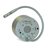
TALK
INDICATING LED
MADE IN U.S.A.
5
OPERATION HINTS
1. Increasing the talk volume control allows the attendant to
speak further from the microphone as well as increasing the
talk channel volume. The optimum distance from the
microphone should be maintained at approximately 3” or
conversations not directed to customers may be heard outside
the booth. Watch the green LED above the TALK volume
control, it should be on ONLY when talking into the gooseneck
microphone.
2. Installing a headset into the Headset jack will allow
communications from the headset and disconnect the speaker
and the gooseneck microphone.
3. The unit will decrease the incoming volume level by
approximately 70% some 30 seconds after the attendant stops
speaking into the microphone. The purpose of this feature is to
decrease the amount of extraneous noise entering the booth.
Normal volume level is restored when the attendant speaks into
the microphone. The muting function can be defeated by
switching the AUTO MUTE switch to the OFF position.
6 TTU-1 P.1.
Be certain to position the
housing so that the
threaded hole can be
positioned properly. If
using tubing, orient the
hole in the direction
which tubing is to exit –
LEFT; RIGHT; TOP
or BOTTOM