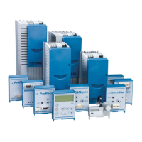
NORDAC SK 5xxE Manual
6 BU 0500 GB
1 GENERAL INFORMATION...........................................................................................................8
1.1 Overview...................................................................................................................9
1.2 Delivery.................................................................................................................. 10
1.3 Scope of supply ..................................................................................................... 10
1.4 Safety and installation information......................................................................... 11
1.5 Approvals............................................................................................................... 12
1.5.1 European EMC guideline ............................................................................................ 12
1.5.2 UL approval................................................................................................................. 12
1.6 Type code / device design..................................................................................... 13
2 ASSEMBLY AND INSTALLATION ........................................................................................... 14
2.1 Installation.............................................................................................................. 14
2.2 Dimensions ............................................................................................................ 15
2.2.1 SK 5xxE, standard version.......................................................................................... 15
2.2.2 SK 5xxE…-CP in ColdPlate version............................................................................ 16
2.3 Mounting dimensions............................................................................................. 17
2.3.1 SK 5xxE, standard version.......................................................................................... 17
2.3.2 SK 5xxE…-CP in ColdPlate version............................................................................ 18
2.4 EMC- Kit ................................................................................................................ 19
2.5 Brake resistor (BR) ................................................................................................ 20
2.5.1 Electrical data BR ....................................................................................................... 21
2.5.2 Dimensions bottom-mounted BR ................................................................................ 22
2.5.3 Dimensions Chassis BR.............................................................................................. 22
2.6 Wiring guidelines ................................................................................................... 23
2.7 Electrical connection.............................................................................................. 24
2.8 Electrical connection of power unit ........................................................................ 25
2.8.1 Mains supply (X1-PE, L1, L2/N, L3)............................................................................ 26
2.8.2 Multi-function relay (X3 – 1, 2, 3, 4) ............................................................................ 26
2.8.3 Motor cable (X2 - U, V, W, earth)................................................................................ 27
2.8.4 Braking resistor connection (X2 - +B, -B).................................................................... 27
2.8.5 Braking resistor connection (X2 - +B, -B).................................................................... 28
2.8.6 Jumper “A” mains input............................................................................................... 29
2.8.7 Jumper “B” motor output ............................................................................................. 29
2.8.8 Interne Verschaltung der Jumper................................................................................ 30
2.9 Electrical connection of the control unit................................................................. 30
2.9.1 Terminal blocks...........................................................................................................31
2.9.2 Details of the SK 5x0E control connections ................................................................ 32
2.9.3 Details of the SK 5x5E control connections ................................................................ 36
2.10 Colour and contact assignments for the incremental encoder. ........................... 40
3 DISPLAY AND OPERATION..................................................................................................... 41
3.1 Modular modules ................................................................................................... 41
3.2 Technology unit overview ...................................................................................... 42
3.2.1 SimpleBox, SK CSX-0 ................................................................................................ 43
3.2.2 ControlBox, SK TU3-CTR ........................................................................................... 45
3.2.3 ParameterBox, SK TU3-PAR ...................................................................................... 50
3.2.4 ParameterBox parameters .......................................................................................... 56
3.2.5 ParameterBox error messages ................................................................................... 58
3.2.6 Profibus module, SK TU3-PBR, …-24V...................................................................... 61
3.2.7 CANopen module, SK TU3-CAO ................................................................................ 61
3.2.8 DeviceNet module, SK TU3-DEV................................................................................ 62
3.2.9 InterBus module, SK TU3-IBS .................................................................................... 62
3.2.10 SK TU3-AS1, AS interface ........................................................................................ 63
3.2.11 PotentiometerBox, SK TU3-POT .............................................................................. 63

 Loading...