1
Table of Contents
Introduction ...................................................................................................................... 2
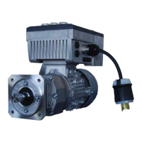
Pump Drive - SK 072.1F-71S/4 CUS with Motor-Mounted SK 200E .............................. 3
Initial Checks ................................................................................................................. 3
Programming ................................................................................................................ 5
Wiring ............................................................................................................................ 6
Diagnostic Cockpits .......................................................................................................... 7
Troubleshooting ............................................................................................................... 8
Additional Resources ..................................................................................................... 10
www.nord.com
ON = 0(4)...20mA
AIN1
AIN2
OFF = 0...10V
24 Vdc Power Input
SK 205E
PE Mains
21 – DIN 1
22 – DIN 2
23 – DIN 3
24 – DIN 4
44 – 24 V
40 - GND
77 – SYS+
78 – SYS-
38 – TF+
39 – TF-
B+ B-
M
U
V
W
PE Motor
DO1 – 1
GND – 40
RY
MB+ – 79
MB- – 80
Digital Input Contacts
System Bus Input
Thermistor (PTC)
Dynamic Braking Resistor
3-
Phase AC
Motor
Status Relay
Motor Brake Coil
RS 485/RS232
Data Cable
Suitable for use on a c ircuit capable of delivering not more than 5000 rms
symmetrical Amperes, 120 Volts maximum (SK 2xxE-xxx-112), 240 Volts
maximum (SK 2xxE-xxx-323) or 500 Volts maximum (SK 2xxE-xxx-340) and
when protected by J class fuses as indicated.
Quick Commission
DIP Switches
DIP Switch 7 ON – Motor data set corresponding to the rated power of the
AC Vector Drive relative to 60 H z. Maximum frequency is set to 60 Hz also.
1 2 3 4 5 6 7 8
ON
AC Vector Drive
L1
L2
L3
3 - Phase AC Input Power
L1
N
1 - Phase AC Input Power
1 = White - 14 - 4 - 20 mA Input
2 = Brown - 12 - Analog Reference
3 = Green - N.C.
4 = Yellow - 21 - Drive Enable
5 = Grey - 22 - Phase Seq. Reversed
6 = Pink - 1 - Drive Running Output
7 = Blue - 40 - Control Reference
8 = Red - N.C

 Loading...