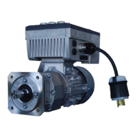
SK 072.1F-71/S4
Motor Mounted SK 200E
Initial Checks – Pump Drive Ctd.
3) CheckACpowerconnections
a.Mains supply voltage must be 200-240VAC,
single-phase. Mains supply voltage must be
connected directly to terminals L1 & N (see
Figure5).Earthgroundisconnectedtooneof
thetwoPEterminals.
b.Confirmmotorleadsareconnectedtoterminals
U-V-W(seeFigure5).
c.Confirmthatthemotoriswiredforlowvoltage,
230VAC (see Figure 6). If motor jumpers
(beneaththeclearplasticbarrier)areconnected
differently,eitherthemotorjumpershavetobe
set as shown, or the motor/drive has to be
replaced.
4) ChecktheM12receptacleandinternalcontrolwiring
a.Confirm that the M12 receptacle is wired per
thediagramshowninFigure10.Ifanyofthe
wires are incorrectly landed, make necessary
changes.Also,ensurethatthewiresaresecurely
fastenedandtheterminalsarescrewedtightly.
b.Figure 10 also shows the pinout of the M12
receptacle. Confirm that the mating cable
receptaclehasamatchingpinout.
5) CheckdriveDIPswitchsettings(seeFigure8).DIP
switch settings other than discussed below may
resultinimproperoperation.
a.FromtheNordfactory,DIPswitch7isturnedon
toconfigurethedrivefora60Hzmotor.
6) Once items 1-5 have been performed, the drive
may be mounted on the motor adapter again.
Lineupthecinchplugsandtightenthe4mmhex
sockethead screws. Input AC power may be
appliedatthistime.
Figure 5 - Motor Terminal Block
U V W
Figure 6 - Motor Power Connections
Figure 7 - Control Wiring Connections
Figure 8 - DIP Switch Settings

 Loading...