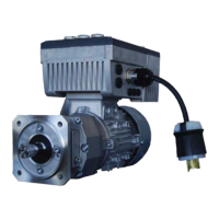
Diagnostic
Cockpits
Diagnostic Cockpits
The SK 200E has 3 diagnostic cockpits that provide
status LEDs, analog input adjustment DIP switches,
and an RJ12 port programming interface. These
cockpitsareaccessible by removing the appropriate
M20screwcap(Figure11).
DrivestatusisindicatedbyLEDDSinthediagnostic
LEDscockpit(seeFigure12).Table2summarizesthe
LED indication, possible causes, and potential rem-
edies. LED BUS-E and BUS-S in the diagnostic LEDs
cockpitwillalwaysremainoff.
In the analog input DIP switches cockpit, the DIP
switchAIN1mustbeintheONposition.Thiswillen-
ableanaloginput1tofunctionasa4-20mAinput.
DS
BUS-E BUS-S
Diagnostic LEDs
ON = 0(4)...20mA
AIN1
AIN2
OFF = 0...10V
Analog Input DIP Switches
Figure 12 - Diagnostic LEDs & DIP Switches
Table 2 - Drive Status LED DS
Drive Status LED Condition Drive State Cause/Remedy
Off Drivenotready
Novoltagepresent.Checkinputmainssupplyconnectionsatpowerter-
minalboard(term.L1&N).
Green on
Drivereadyandnotin
OLmode
Driveisrunningnormallyandtherearenowarningsoroverloadspresent.
Green flashing
0.5Hzashingfrequency:
Standby
Mainsandcontrolvoltagespresent.Drivereadytoacceptruncommand.
2Hzashingfrequency:
DriveInhibited
Operatingconditionsnotmetandunitisnotabletorun.Checkparam-
eterP700[-03]foractualcauseofdriveinhibition.
Alternating Green/Red
0.5Hzashingfrequency:
Warning
Driveisrunning,butoperatingconditionsareoutofspec.Ifunitcon-
tinuestorunundertheseconditions,drivewilleventuallytrip.Check
parameterP700[-02]foractualwarningmessage.
1–25Hzashingfrequency:
DriverunninginOLmode
Thedriveisrunningbuttheinverterisoverloaded.Thehighertheash-
ingfrequency,thehighertheoverload.Checkthedrivenequipmentto
ensuretheunitisn’toverloaded.
Red on/flashing Drivefaulted
Operatingconditionsofthedrivecausedtheunittofault.Thenumberof
ashesindicatesthefaultnumber.Faultdescriptionsandremediescanbe
foundinsection7.2oftheSK200EoperationmanualBU0200.
RJ12Port
AnalogIput
DIPSwitches
Figure 11 - Diagnostic Cockpits
Diagnostic
LED's
DS
BUS-E BUS-S

 Loading...