Do you have a question about the Nordelettronica KIT-NE185-12S and is the answer not in the manual?
| Brand | Nordelettronica |
|---|---|
| Model | KIT-NE185-12S |
| Category | Control Panel |
| Language | English |
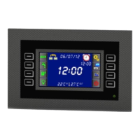
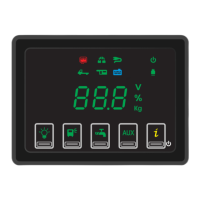
Details button functions, display variations, and indicator symbols for load status.
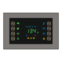
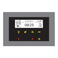
Explains screen displays, temperature readings, voltage symbols, and indicator icons.
Guides on setting date, time, alarms, brightness, and sleep mode.
Outlines power usage in different operational modes and states.
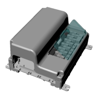
Describes serial, temperature probe, and remote probe connectors.
Explains the role of the buffer battery for maintaining time during power outages.
Details the function and amperage of each fuse (F1-F9) for circuit protection.
Explains how power is activated for various system functions from the control panel.
Conditions for enabling coupler and fridge relays via the D+ signal.
Describes how to activate side markers using negative or positive control.
Explains the recharge process for the starting battery when connected.
Defines the input connection for the auto battery (B1).
Defines the input connection for the service battery (B2).
Specifies the connection point for the main negative terminal.
Details the positive output for activating charges with engine running.
Identifies the multiple negative terminal connections.
Defines connections for Lights_1 and Lights_2.
Specifies outputs for Step and Webasto/Auxiliary.
Details direct and relay-activated fridge output connections.
Lists various power outputs including AUX, pump, and courtesy lights.
Defines D+ input from alternator and power on from charger.
Specifies connections for full recycle tanks R1.
Defines connections for full recycle tanks R2 and R3.
Lists connections for various levels of the fresh water tank S1.
4-pole connector for linking the control panel.
Defines D+ control input and side marker signal inputs.
Specifies the output connection for the left side marker.
Specifies the output connection for the right side marker.
Defines connections for car battery, service battery, and ignition for solar panels.
Explains warranty void conditions due to improper use and producer's liability.
Notes that data may be altered without notice for continuous technical improvement.
Provides company address, telephone, fax, and website details.