Do you have a question about the Nordelettronica NE185_20G and is the answer not in the manual?
| Brand | Nordelettronica |
|---|---|
| Model | NE185_20G |
| Category | Power Supply |
| Language | English |
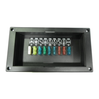
Detailed list and function of all fuses (F1-F9) used in the NE185 shunt.
Explains how the NE185 shunt operates under different conditions and inputs.
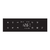
Control panel activation of lights, external light, and pump, with low voltage cut-off.
Automatic charging of the car battery via the 230V main supply.
Activation methods for the side-marker output using negative or positive control.
Enabling of coupler and fridge relays based on D+ input and engine status.
Important notes regarding DC/DC converter usage and its effect on the coupler relay.
Description of the JP1 connector and its negative pin assignments.
Details for the JP2 connector, including connections for lights outputs.
Information on the JP3 connector for step and Truma outputs.
Specifications for the JP4 connector related to fridge outputs and gas ignition.
Overview of the JP5 connector for various power outputs like AUX, heater, and pump.
Details on the JP7 connector for recycle tank R1 status monitoring.
Information on the JP8 connector for recycle tanks R2 and R3 status.
Specifications for the JP9 connector related to the water tank level sensor S1.
Description of the JP11 connector for the control panel interface.
Details for JP13 regarding D+ input, side marker, and power main connections.
Specifications for the JP14 connector for the left side marker output.
Details on the JP15 connector for the right side marker output.
Information on the JP16 connector for solar panel options.
Description of the J1 connector for car battery input.
Details for the J2 connector for service battery input.
Description of the J3 connector for negative ground connection.
Specifications for J4/J5 connectors providing D+ output for various functions.
Details on the J14 connector for DC-DC converter presence detection.
Description of the J15 connector for negative ground connection.